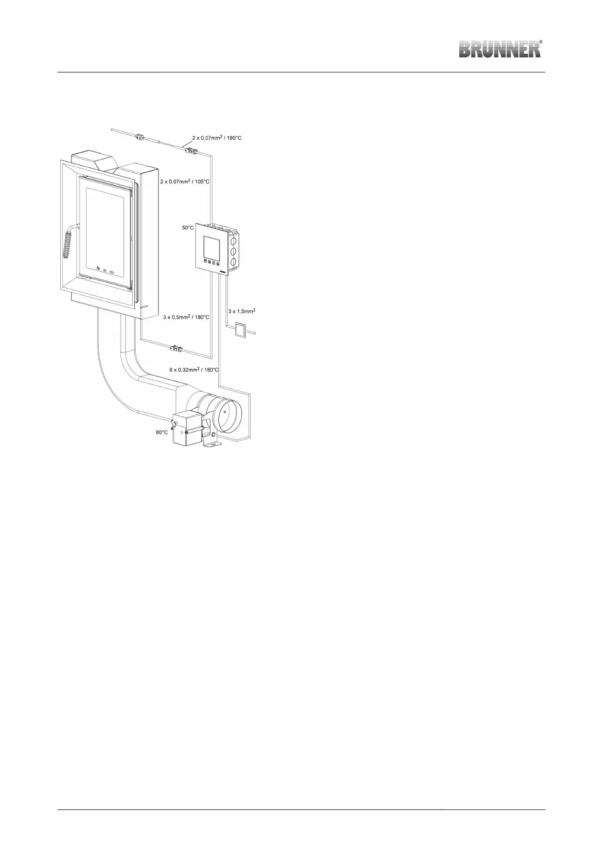
12 INSTALLATION NOTES FOR EAS
Illustration 7: Schematic layout of EAS
The indicated temperatures are maximal permissible tempera-
tures of components!
When selecting place of installation, keep in mind the max. per-
mitted temperature for the component. Components cannot be
installed in closed spaces; proper ventilation must ensure suffi-
cient heat discharge.
The indicated wiring dimensions are minimal dimensions!
The installation of electronic components must be carefully prepared and performed. Please note the follow-
ing:
• The flush-mounting box for electronics must be fitted in level and clean, to ensure easy, tension-free instal-
lation of electronics.
• Prevent any physical contact with electronic components - possible electrostatic discharge can damage
them.
• Humidity can affect electronic components. Therefore, it is very important to ensure clean and dry installa-
tion of electronics.
• If possible, avoid installation of electronic components in exterior walls to prevent risk of corrosion at tem-
peratures below dew point.
• Do not install the control unit within the heated tiled stove shell.
• The selected type of installation must ensure that temperatures will not exceed +40# (104°F) and the unit
will be not exposed to direct heat radiation.
To avoid risk of damage, all cable conduits leading from electronics into the heating chamber must enter at
the bottom of the stove casing. Cable conduits cannot end in upper parts of the heating chamber due to ex-
cessive temperature.
All electronic components must be accessible after installation for revision and replacement.
20 Installation Guide KSO 33 (1.12) © 2021 Brunner GmbH