13.5 ASSEMBLY OF EAS COMPONENTS
Electronic combustion control EAS - additional parts on KSO
Component Assembly Assembled by
Gear motor on base frame assembled by Brunner
Thermocouple Installed above stove door after stove front assembly
Door contact switch Installed below stove door after stove front assembly
Bus wiring, thermocouple wiring
and door contact switch wiring
Connection from the EAS to the
pedestal area under base frame
after assembly of EAS compo-
nents and preparation of pedestal
sheet metal cover
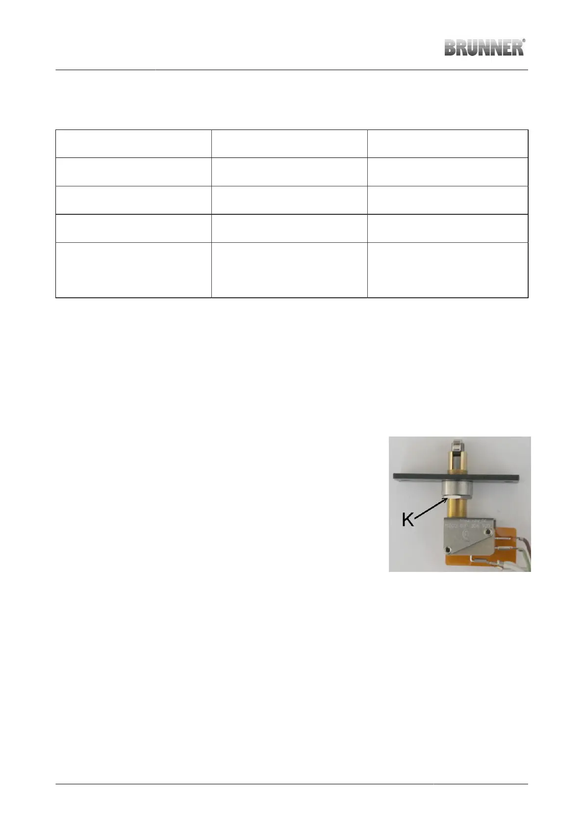
Door contact switch installation
The door contact switch is installed in the middle of the front at the lower transverse web. The necessary
screws are fitted on the left and right side of the opening. Because the door was removed for stove front
assembly and readjusted in height after assembly, it can be necessary to adjust the position of the door
contact switch.
The connection with EAS is made with a special door contact switch wiring, which is coupled with the
switch via plug-in connector.
Working step Note
1. Measure the distance from
the lower edge of door to the
transverse web of front
The door must be already adjusted in
height.
2. Check/adjust the height of
door contact
The protrusion of door contact switch
(from the top of roller to the cast iron
insertion plate) must be approx. 3mm
greater than the height of lower edge of
door above the transverse web of stove
front.
For adjustment, loosen the nut
“K” (SW16), turn the cast iron plate until
the desired height is reached, and secure
the adjustment by tightening the nut “K”.
The switch must be in the shown position,
to allow the actuating roller for rotation
while the door is closed.
Illustration 54: Door contact switch
38 Installation Guide KSO 33 (1.12) © 2021 Brunner GmbH