3. Remove the countersunk
screws
Remove both countersunk screws from
the stove front transverse web at the bot-
tom. Open the door.
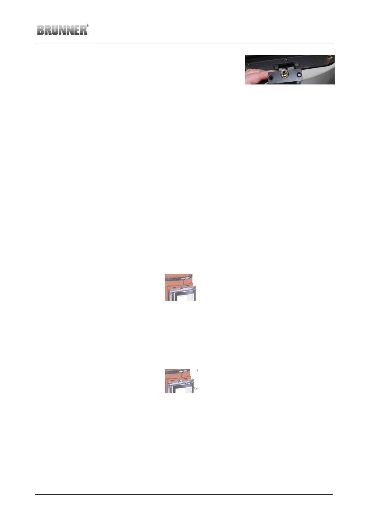
4. Install the door contact Pull down the connector and wiring
through the opening in the stove front
transverse web and install the door con-
tact switch. Mind the switch position (clos-
er to the front).
Illustration 55: Placing the door
contact switch on the stove front
transverse web
5. Checking the switch func-
tion
Close the door carefully and check the switch function. The door must
move easily across the switch and a clear ‘clicking sound’ must be heard.
6. Connection door contact -
EAS
The piece of wire from the door contact is connected to the specified door
contact wiring at the stove bottom.
For future exchange of the door contact switch it is helpful to have enough
of ‘spare wiring length’, allowing for connector access when the door con-
tact switch is removed.
Thermocouple installation
The thermocouple is placed in the middle above the stove door. The
necessary opening in combustion chamber must be made (drill size
d8). A special M12 screw with d8 hole is provided as drilling aid, de-
termining the position and drilling angle.
Working step Note
1. Drilling through the
combustion chamber
Use the M12 screw
with d8 hole as a
drilling template,
drilling through the in-
ner shell of combus-
tion chamber
2. Remove the M12-
d8 screw
Drilling aid is no
longer needed
Illustration 56: Drilling aid
in front
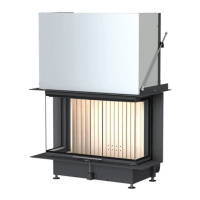
3. Turn the thermo-
couple in
Insert the thermocou-
ple carefully and turn
it in
Illustration 57: Thermo-
couple turned in
© 2021 Brunner GmbH Installation Guide KSO 33 (1.12) 39