4. Lay the wiring at
the side of the front
The thermocouple
can be bent once.
The wiring route must
be free from obsta-
cles, to allow for ex-
change of thermo-
couple after external
cladding is assem-
bled.
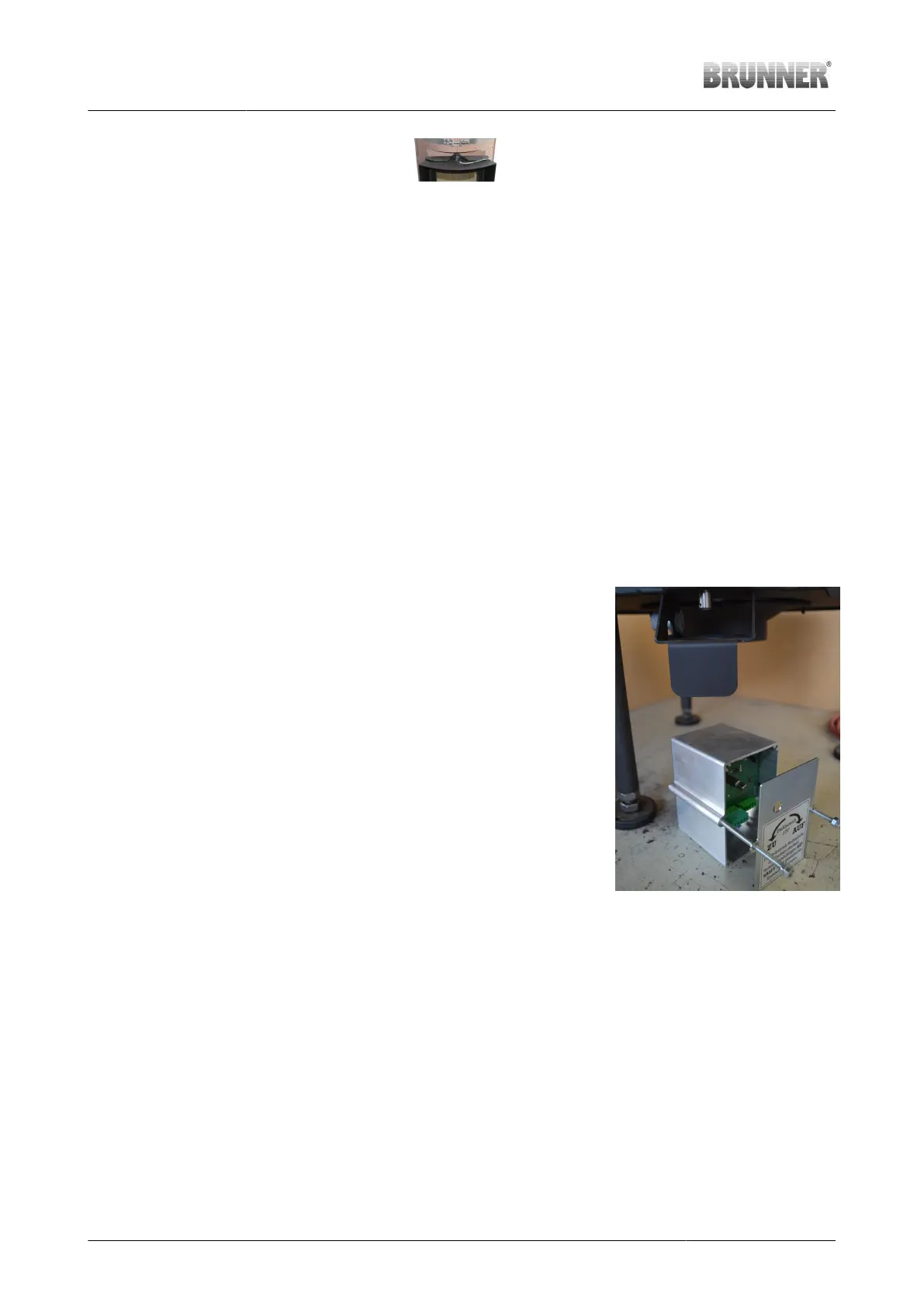
5. Connection with
EAS
At the bottom of the
stove, the thermocou-
ple wiring is connect-
ed with the thermo-
couple connector.
Illustration 58: Route of
thermocouple wiring
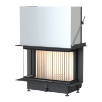
Connection of gear motor to EAS board
Working step Note
Unscrew the motor box After loosening the two M5x90 screws,
the aluminium motor housing and the
housing cover can be detached and re-
moved at the bottom.
Illustration 59: Components of mo-
tor box
40 Installation Guide KSO 33 (1.12) © 2021 Brunner GmbH