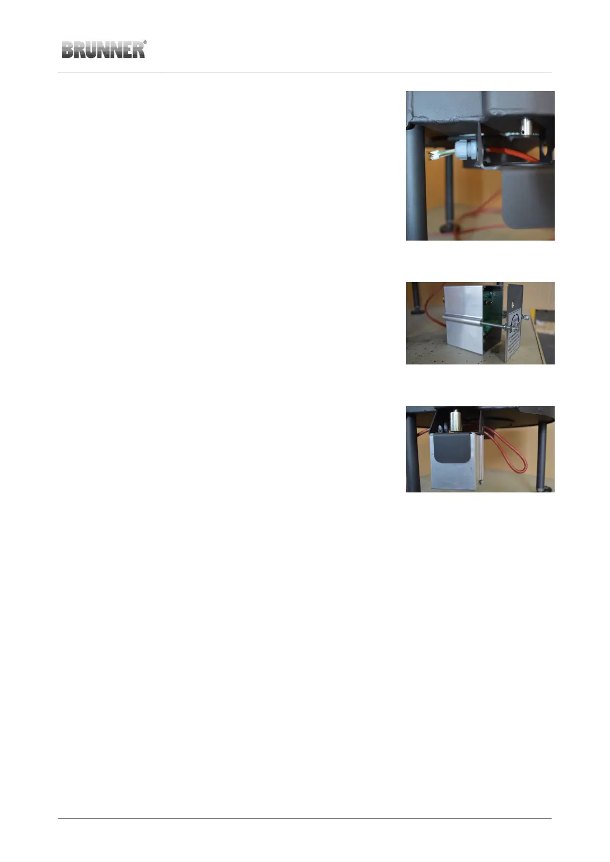
Pull the bus wiring through the
cable gland on the motor sup-
porting bracket
Undo the cap nut of the cable gland and
push the wiring from inside through the
cable gland.
Illustration 60: Bus wiring in cable
gland
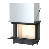
Connect the bus wiring to K1 Push the bus wiring through the rectangu-
lar opening on the back of the aluminium
housing for the gear motor, and connect it
to the free connector
Install the motor box Put the screws, the housing cover and
aluminium box together and affix with
screws to the motor supporting bracket.
Illustration 61: Connected bus
wiring
Affix the bus wiring with the
cable gland
Pull the bus wiring through the cable
gland while leaving a spare length of ap-
prox. 40cm (approx. 16 inches) and tight-
en the cap nut of the cable gland.
Illustration 62: Drive installed - with
spare cable length for motor ex-
change
© 2021 Brunner GmbH Installation Guide KSO 33 (1.12) 41