13.2 ASSEMBLY OF COMBUSTION CHAMBER
The combustion chamber is made of two shells - the inner shell consists of fire-resistant concrete and the
outer shell of heat accumulating material.
The combustion air is supplied at the bottom of base frame and enters through slots on the upper side of
base frame into the round gap between the inner and outer shell. During assembly, make sure that all air in-
take openings are without any obstacles!
The inner shell is set dry without any additional materials. The parts are movable due to sealing ropes in their
grooves, which allows for thermal expansion.
The tightness of the external shell is essential for the accumulation stove function. Therefore, all compo-
nents of the external shell must be tightened with the high-temperature sealant (in delivery contents), in ad-
dition to the existing sealing ropes. After the components are set, all external joints have to be filled with this
sealant, even on the contact surfaces of the stove front. Stove casing must be sealed before the external
stove cladding is laid!
During all works, make sure that the sealing ropes between stove casing parts fit tight and get not damaged
during assembly. The contact faces of components must be kept free from dust.
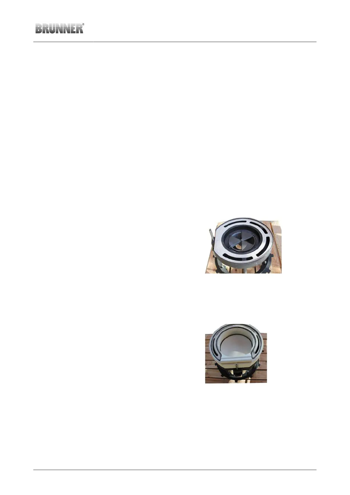
Completion of base frame
Working steps: Note
1. Check the smooth move-
ment of the air adjusting lever
The air adjusting lever part is
included in the attached ac-
cessory kit
2. Put the ‘fibrous material bot-
tom plate’ in place
Air intake openings must be
free
3. Put the ‘bottom revision cov-
er’ in place
Illustration 12: Fibrous bottom plate placed on
base frame
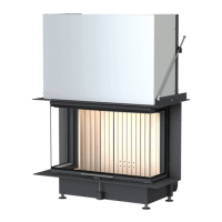
Setting the base ring and bottom plate
Working step Note
1. Put the ‘combustion cham-
ber base ring’ in centric posi-
tion on the base frame seal
Align the base ring in the mid-
dle on the air adjusting lever;
the air intake openings for the
base unit must be free from
obstacles.
2. Put the ‘bottom plate’ in
place
The bottom plate is laid loose.
This allows for access to the
air adjusting mechanism inside
the base frame.
Illustration 13: Base ring and bottom plate in
place
Setting the combustion chamber walls
Working step Note
© 2021 Brunner GmbH Installation Guide KSO 33 (1.12) 23