926SB: Installation, Start-up, Operating, Service and Maintenance Instructions
Manufacturer reserves the right to change, at any time, specifications and designs without notice and without obligations.
42
A230011
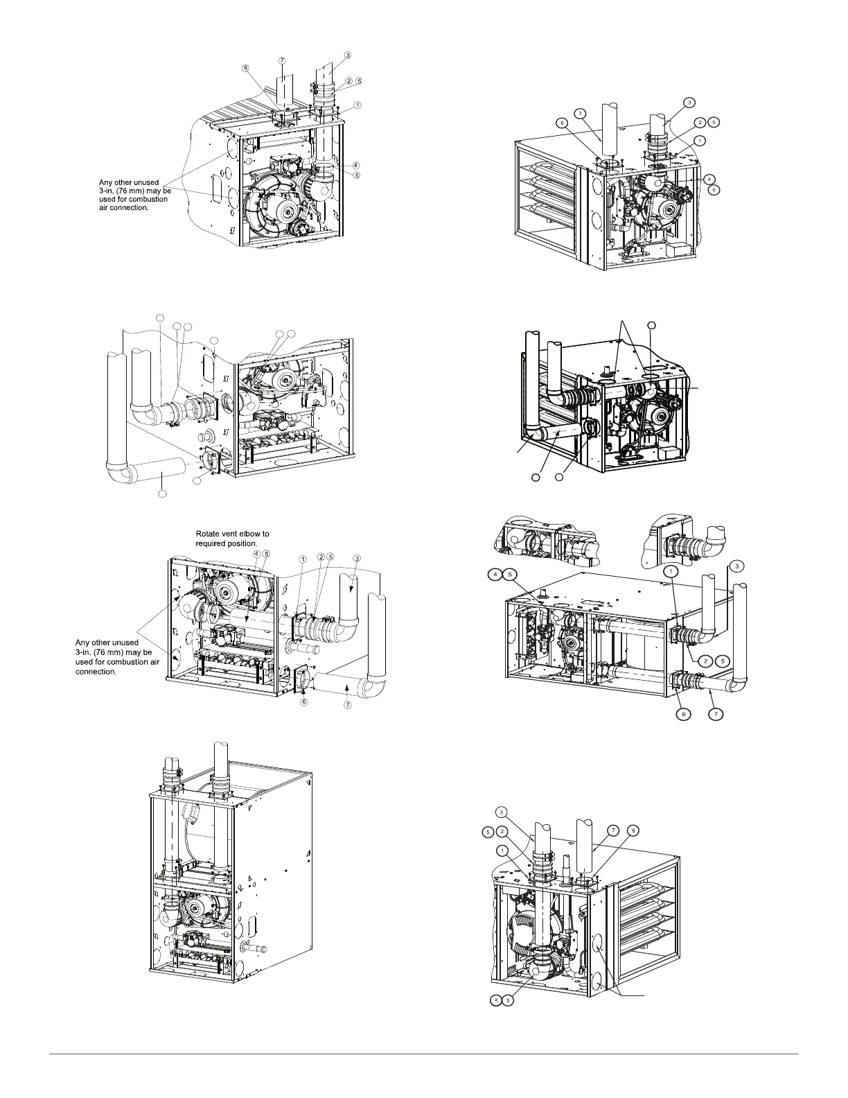
UPFLOW VERTICAL VENT
Fig. 54 – Upflow Configuration (Appearance May Vary)
See “Notes for Venting Options”
A11311A
DOWNFLOW LEFT CONFIGURATION
A230013
DOWNFLOW RIGHT CONFIGURATION
A11313A
DOWNFLOW VERTICAL
Fig. 55 – Downflow Configurations (Appearance May Vary)
See “Notes for Venting Options”
A11327A
HORIZONTAL LEFT-VERTICAL VENT CONFIGURATION
A11328A
HORIZONAL LEFT-LEFT VENT CONFIGURATION
A11329A
HORIZONTAL LEFT-RIGHT VENT CONFIGURATION
Fig. 56 – Horizontal Left (Appearance May Vary)
See “Notes for Venting Options”
A11337
HORIZONTAL RIGHT-VERTICAL VENT CONFIGURATION
1
2
3
4
5
6
7
5
Rotate vent elbow to
required position.
Requires Accessory Internal Vent Kit.
See Product Data for current kit number.
6
4
Alternate combustion air
connection.
Rotate vent
elbow to
required
position.
4
5
Vent Pipe
Requires Accessory Vent Kit
See Product Data for
Current Kit Number
ALTERNATE
COMBUSTION
AIR CONNECTIONS