926SB: Installation, Start-up, Operating, Service and Maintenance Instructions
Manufacturer reserves the right to change, at any time, specifications and designs without notice and without obligations.
52
FURNACE CONTROL PROGRAMMING
AND NAVIGATION
On-Board Control Method
This furnace model is equipped with an on-board 3-digit LCD display
with pushbutton navigation for the adjustment of operating parameters,
diagnostics, and service. The control board must be powered to use the
display and pushbuttons. Upon startup, the control will alternate
displaying the Model Program Number (PRG) and Software Version
(uEr). The control board has been programmed at the factory with a
Model Program Number specific to the furnace product number. The
correct Model Program Number is shown on the furnace rating plate.
The system’s status is displayed after startup or after no control buttons
have been pressed for 60 seconds. Status Code LED will also be
illuminated or blinking when displaying the system status. The codes
which indicate the current operating mode of the system as shown in
Table 21.
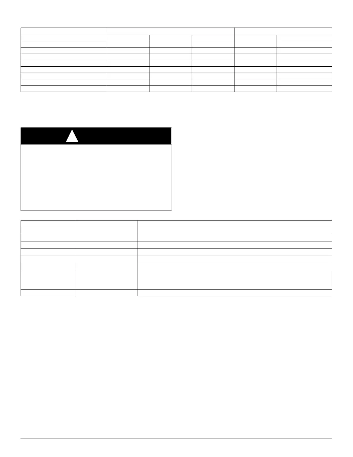
Table 20 – Default Airflow Settings
Default Airflow Settings
*
*. Setting #1 is the default setting for Constant Fan
Designated Airflow Settings
Unit Size Heating High Cooling Low Cooling Heating Const. Fan
30040V14 13 25 17 (9 - 15) (1 - 3)
36040V17 9 24 13 (5 - 10) (1 - 3)
36060V14 15 25 15 (10 - 15) (1 - 3)
48060V17 10 25 13 (6 - 11) (1 - 8)
48080V17 15 24 14 (9 - 16) (1 - 3)
60080V21 9 25 14 (6 - 12) (1 - 8)
60100V21 13 24 12 (10 - 14) (1 - 6)
66120V24 17 22 12 (12 - 17) (1 - 3)
CAUTION
!
ELECTRICAL SHOCK HAZARD
Failure to follow this warning could result in personal injury, or death.
Blower access door switch removes 115-V power to control. No
component operation can occur unless switch is closed. Caution must
be taken when manually closing this switch for service purposes.
Do not tape or permanently allow the door switch to be bypassed.
Temporarily depress the door switch with one hand while accessing the
service buttons with your other hand. Do not touch uninsulated
electrical components.
Table 21 – System Status Display Codes
Display Operating Mode Notes:
iDl
Idle/Standby Mode No active demands
Ht
Heating Mode Gas Heating active
CL2
High Cooling Mode Cooling or Heat Pump active
CL1
Low Cooling Mode Cooling or Heat Pump active
Hpd
Heat Pump Defrost Mode Gas Heating cycle active during Heat Pump Defrost cycle
Cfn, CF2, CF3
Continuous Fan Mode Continuous Fan active
bLr
Secondary Unit Operating
Blower during
Cfn, CL, or
Ht
Only used when control is the secondary furnace of a twinned furnace system and primary
furnace is active
##.# Active Status Code See Fig. 60 or Furnace Service Label for codes