926SB: Installation, Start-up, Operating, Service and Maintenance Instructions
Manufacturer reserves the right to change, at any time, specifications and designs without notice and without obligations.
6
The furnace should be sized to provide 100 percent of the design heating
load requirement plus any margin that occurs because of furnace model
size capacity increments. None of the furnace model sizes can be used if
the heating load is 20,000 BTU or lower. Use Air Conditioning
Contractors of America (Manual J and S); American Society of Heating,
Refrigerating, and Air-Conditioning Engineers; or other approved
engineering method to calculate heating load estimates and select the
furnace. Excessive oversizing of the furnace may cause the furnace
and/or vent to fail prematurely, customer discomfort and/or vent
freezing.
Failure to follow these guidelines is considered faulty installation and/or
misapplication of the furnace; and resulting failure, damage, or repairs
may impact warranty coverage.
For accessory installation details, refer to the applicable instruction
literature.
NOTE: Remove all shipping materials, loose parts bag, and literature
before operating the furnace. See Table 3.
Table 3 – Loose Parts Bag
NOTE: The 40K models are the only furnaces that receive the outlet
restrictor in loose parts bag. See Maximum Equivalent Vent Length
Table for usage.
A12182
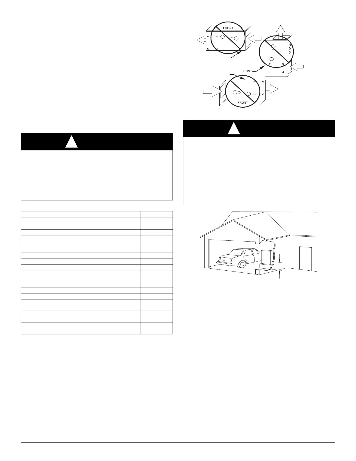
Fig. 4 – Prohibited Installations
A93044
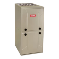
Fig. 5 – Installation in a Garage
CODES AND STANDARDS
Follow all national and local codes and standards in addition to these
instructions. The installation must comply with regulations of the
serving gas supplier, local building, heating, plumbing, and other codes.
In absence of local codes, the installation must comply with the national
codes listed below and all authorities having jurisdiction.
In the United States and Canada, follow all codes and standards for the
following:
Safety
• US: Current edition of National Fuel Gas Code NFPA 54/ANSI
Z223.1 and the Installation Standards, Warm Air Heating and Air
Conditioning Systems ANSI/NFPA 90B
• CANADA: Current edition of National Standard of Canada, Natural
Gas and Propane Installation Code (NSCNGPIC) CAN/CSA B149.1
General Installation
• US: NFPA 54/ANSI Z223.1 and the NFPA 90B. For copies, contact
the National Fire Protection Association Inc., Batterymarch Park,
Quincy, MA 02269; or for only the NFPA 54/ANSI Z223.1 contact the
WARNING
!
FIRE HAZARD
Failure to follow this warning could result in personal injury, death
and/or property damage.
Do not install the furnace on its back or hang furnace with control
compartment facing downward. Safety control operation will be
adversely affected. Never connect return-air ducts to the back of the
furnace. See Fig. 4.
DESCRIPTION QUANTITY
Outlet Restrictor Plate (provided with 40K BTUh
furnaces only; see Note)
1
Air Intake Pipe Flange 1
Vent Pipe Flange 1
Pipe Flange Gaskets 2
Sharp Tip Screws (Vent and Inlet Flanges) 10
Vent Pipe Coupling 1
Vent Pipe Coupling Clamps 2
Pressure Switch Tube 1
Rubber Drain Elbow 1
Drain Tube Clamps 4
1/2-in. CPVC to 3/4-in. PVC Pipe Adapter 1
Gas Line Grommet 1
Junction Box Cover 1
Junction Box Base 1
Green Ground Screw 1
Blunt Tip Screws (Junction Box) 3
Thermostat Wire Grommet 1
Drain Extension Tube (Z-pipe) (Provided separately in
furnace)
1
WARNING
!
FIRE, INJURY OR DEATH HAZARD
Failure to follow this warning could result in personal injury, death
and/or property damage.
When the furnace is installed in a residential garage, the burners and
burner ignition devices must be located at least 18 in. (457 mm) above
the floor. The furnace must be located or protected to avoid damage by
vehicles. When the furnace is installed in a public garage, airplane
hangar, or other building having a hazardous atmosphere, the furnace
must be installed in accordance with the current edition of NFPA
54/ANSI Z223.1 or CAN/CSA B149.2. See Fig. 5.
BACK POSITIONED
DOWNWARD
AIR RETURN
CUT IN BACK
BACK POSITIONED
UPWARD
18-IN. (457.2 mm)
MINIMUM TO BURNERS