926SB: Installation, Start-up, Operating, Service and Maintenance Instructions
Manufacturer reserves the right to change, at any time, specifications and designs without notice and without obligations.
11
2. An attic or crawlspace may be considered a space that freely
communicates with the outdoors provided there are adequate
permanent ventilation openings directly to outdoors having free
area of at least 1-in.2/4,000 BTUh of total input rating for all gas
appliances in the space.
3. In spaces that use the Indoor Combustion Air Method, infiltration
should be adequate to provide air for combustion, permanent
ventilation and dilution of flue gases. However, in buildings with
unusually tight construction, additional air MUST be provided
using the methods described in the Outdoor Combustion Air
Method section.
4. Unusually tight construction is defined as Construction with:
a. Walls and ceilings exposed to the outdoors have a continuous,
sealed vapor barrier. Openings are gasketed or sealed and
b. Doors and openable windows are weatherstripped and
c. Other openings are caulked or sealed. These include joints
around window and door frames, between sole plates and floors,
between wall-ceiling joints, between wall panels, at penetrations
for plumbing, electrical and gas lines, etc.
Combination of Indoor and Outdoor Air
1. Indoor openings shall comply with the Indoor Combustion Air
Method below and,
2. Outdoor openings shall be located as required in the Outdoor
Combustion Air Method mentioned previously and,
3. Outdoor openings shall be sized as follows:
a. Calculate the Ratio of all Indoor Space volume divided by
required volume for Indoor Combustion Air Method below.
b. Outdoor opening size reduction Factor is 1 minus the Ratio in a.
above.
c. Minimum size of Outdoor openings shall be the size required in
Outdoor Combustion Air Method above multiplied by reduction
Factor in b. above. The minimum dimension of air openings shall
be not less than 3 in. (80 mm).
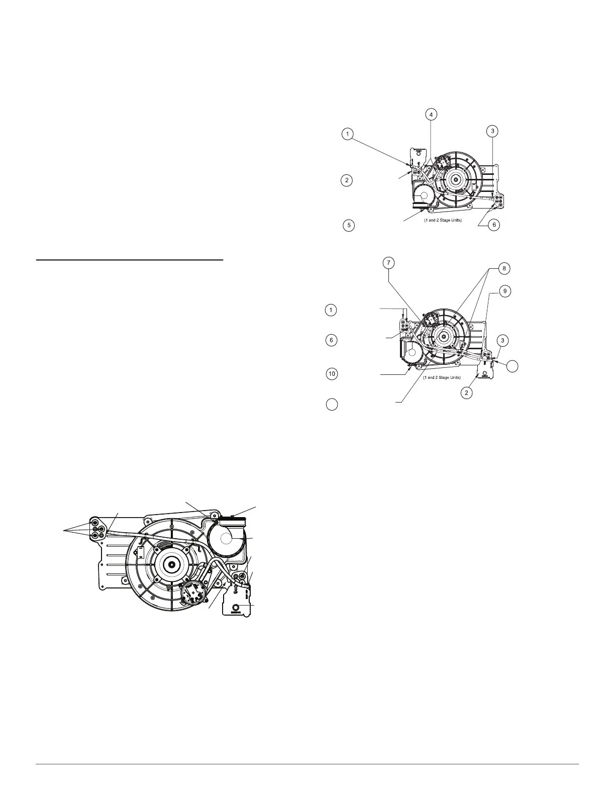
CONDENSATE TRAP
Condensate Trap - Upflow Orientation
When the furnace is installed in the upflow position, it is not necessary
to relocate the condensate trap or associated tubing. Refer to Fig. 8 for
upflow condensate trap information. Refer to Condensate Drain section
for information how to install the condensate drain.
A11307
Fig. 8 – Upflow Trap Configuration
(Appearance may vary)
Condensate Trap - Downflow Orientation.
When the furnace is installed in the downflow position, the condensate
trap will be initially located at the upper left corner of the collector box,
as received from the factory. See the top image in Fig. 9. When the
furnace is installed in the downflow orientation, the condensate trap
must be relocated for proper condensate drainage. See the bottom image
in Fig. 9.
To Relocate the Condensate Trap:
• Orient the furnace in the downflow position.
• Fig. 9 shows the condensate trap and tubing before and after
relocation. Refer to Fig. 9 to begin the trap conversion.
• Refer to Condensate Drain section for information how to install the
condensate drain.
A11587
Fig. 9 – Downflow Trap Configuration
(Appearance may vary)
Condensate Trap - Horizontal Orientation.
When the furnace is installed in the horizontal right position, the
condensate trap will be initially located at the bottom of the collector
box, as received from the factory. See the top image in Fig. 10. When the
furnace is installed in the horizontal left position, the condensate trap
will be initially located at the top of the collector box, as received from
the factory. See the top image in Fig. 11. In both cases the trap must be
repositioned on the collector box for proper condensate drainage. See the
bottom images in Fig. 10 and Fig. 11.
A field-supplied, accessory Horizontal Installation Kit (trap grommet) is
required for all direct-vent horizontal installations (only). The kit
contains a rubber casing grommet designed to seal between the furnace
casing and the condensate trap. See Fig. 18.
Condensate Trap
Relief Port
Collector Box
Plugs
Pressure Switch
Port
Condensate Trap
Outlet
Condensate Trap
Relief Port
Collector Box
Plug
Vent Elbow
Vent Elbow Clamp
Vent Pipe Clamp
UPFLOW TRAP CONFIGURATION
1 & 2 Stage Units
Remove relief tube from relief
port on condensate trap.
Remove the screw
that secures the trap
to the collector box and
remove trap.
Loosen clamp on inlet
to vent elbow.
Remove pressure switch tube from
front pressure switch and discard. A
new tube is shipped in the loose parts bag.
Remove tube from relief port.
Remove middle and bottom
plugs. DO NOT DISCARD.
Unconverted Factory Configuration as
Viewed in the Downflow Orientation
Install the two plugs
previously removed
on the open ports
of the collector box.
Connect relief tube
to port on collector
box.
Rotate elbow to
desired position and
tighten clamp to
15 lb.ïin.
Slide tube in standïoffs
to adjust length.
Connect the new pressure switch
tube from Loose Parts bag to
port on front pressure switch.
Route tube through inducer
standïoffs to adjust position
of the tube.
Trim excess tube.
Connect pressure switch
tube to port on collector
box.
Attach condensate trap
with screw to collector box.
Connect relief tube to
relief port on condensate
trap.
Align condensate trap
over middle and bottom
ports of collector box.
4
5
Downflow Trap Configuration