926SB: Installation, Start-up, Operating, Service and Maintenance Instructions
Manufacturer reserves the right to change, at any time, specifications and designs without notice and without obligations.
12
A230046
A230047
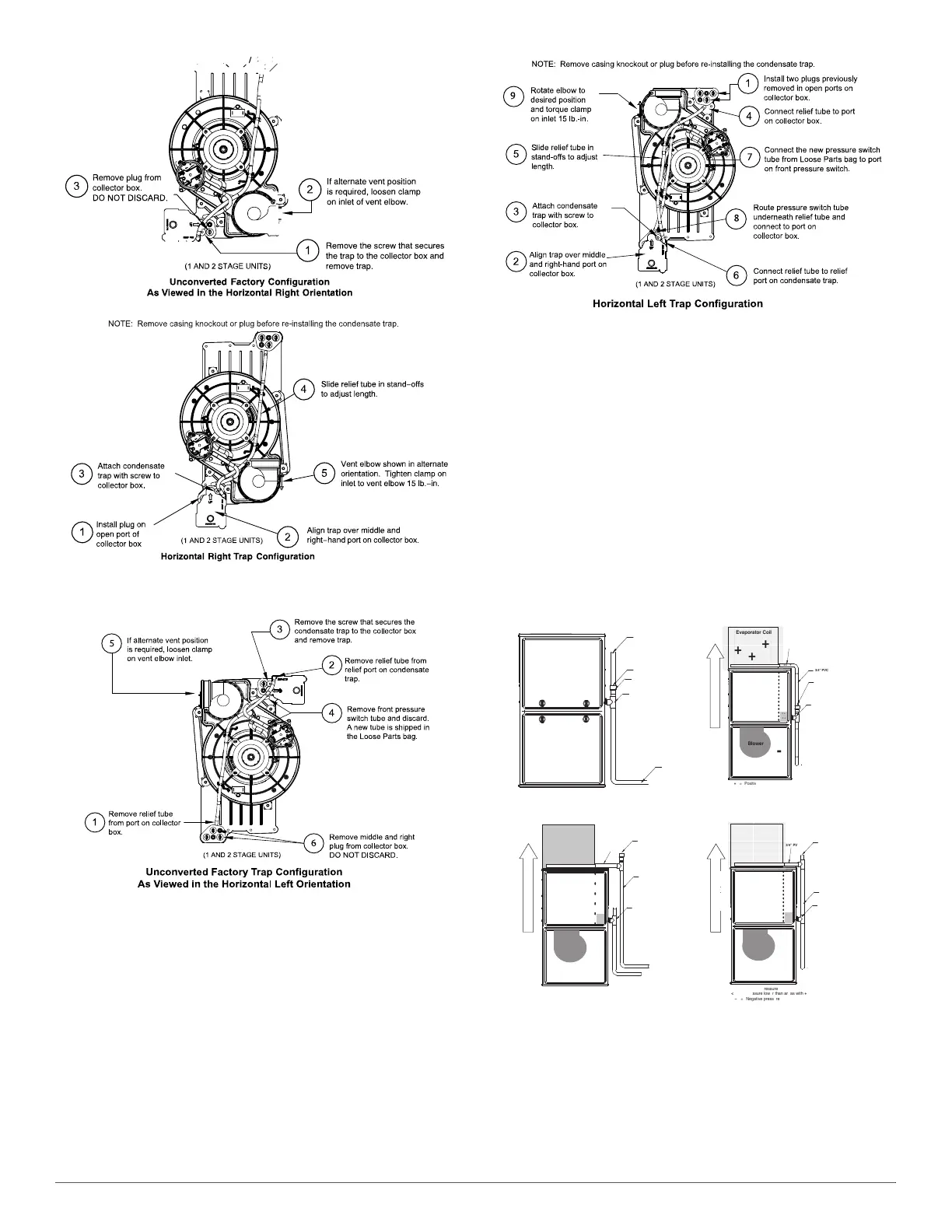
Fig. 10 – Horizontal Right Trap Configuration
(Appearance may vary)
A230048
A230049
Fig. 11 – Horizontal Left Configuration
(Appearance may vary)
To Relocate the Condensate Trap:
• Remove the knockout or plug in the casing for the condensate trap.
• Install the grommet in the casing when required for direct-vent
horizontal applications.
• Orient the furnace in the desired position.
• Allow for 2 in. (51 mm) of clearance underneath the furnace for the
condensate trap and drain line.
• Fig. 10 shows the condensate trap and tubing before and after
relocation in the horizontal right position.
• Fig. 11 shows the condensate trap and tubing before and after
relocation in the horizontal left position.
• Refer to the appropriate figure to begin the trap conversion.
• Refer to Condensate Drain section for information how to install the
condensate drain.
A170135
Fig. 12 – Example of Field Drain Attachment
Air
gap
here
Open
standpipeLQKLJK
PLQLPXP
for
coilor
humidifier
drain
TEE
(1/2”
CPVC
to
3/4”
PVC
adapter
from
loose
parts
bag.)
To
open
drain
&RLORUKXPLGLILHUGUDLQ
ZKHQXVHG
+
+
+
Condensing
Furnace
-
-
-
-
-
ÄÄÄÄÄÄÄÄÄÄ
ÄÄÄÄÄÄÄÄÄÄ
ÄÄÄÄÄÄÄÄÄÄ
ÄÄÄÄÄÄÄÄÄÄ
ÄÄÄÄÄÄÄÄÄÄ
ÄÄÄÄÄÄÄÄÄÄ
ÄÄÄÄÄÄÄÄÄÄ
Evaporator Coil
+
+
+
< +
< +
< +
+
Blower
-
3/4”
PVC
3/4
3/4
3/4
3/4
+ = Positive pressure
< + = Pressure lower than areas with +
ï = Negative pressure
+
3/4”
PVC
DIRECTION
OF
AIRFLOW
+
+
+
3/4
Open standpipeLQKLJKPLQLPXP
Air
gap
required
when
another
drain
is
connected
to
furnace
drain.
+
TEE
(1/2”
CPVC
to
3/4”
PVC
adapter
from
loose
parts
bag.)
+
+
+
Condensing
Furnace
ï
ï
ï
ï
ï
Evaporator Coil
+
+
+
< +
< + < +
+
Blower
ï
3/4” PVC
3/4
1/2”CPVCorlarger*
+
= Positive pressure
< +
= Pressure lower than areas with +
( = Negative pressure
+
3/4” PVC
DIRECTION OF AIRFLOW
+
+
+
+
3/4
3/4
3/4
3/4
Open
standpipe
(Optional
when coil drain
is
not
connected to
furnace
drain.)
Recommend “T” fitting
standpipe of same
diameteror larger
H[WHQGLQJXSZDUG
ZLWKPLQLPXPLQFKhigh
+
+
+
Condensing
Furnace
-
-
-
-
-
Evaporator
ÄÄÄÄÄÄÄÄÄ
Coil
ÄÄÄÄÄÄÄÄÄ
+
ÄÄÄÄÄÄÄÄÄ
+
ÄÄÄÄÄÄÄÄÄ
+
ÄÄÄÄÄÄÄÄÄ
ÄÄÄÄÄÄÄÄÄ
+
ÄÄÄÄÄÄÄÄÄ
< +
< +
< +
+
Blower
-
3/4”
PVC
3/4
3/4
3/4
3/4
3/4
3/4
+ = Positive pressure
< + = Pressure lower than areas with +
ï = Negative pressure
3/4”
PVC
Open
standpipe
(Optional
when
coil
drain
is
not
connected
to
furnace
drain.)
TEE
(1/2”
CPVC
to
3/4”
PVC
adapter
from
loose
parts
bag.)
DIRECTIONOFAIRFLOW