926SB: Installation, Start-up, Operating, Service and Maintenance Instructions
Manufacturer reserves the right to change, at any time, specifications and designs without notice and without obligations.
23
Ductwork Acoustical Treatment
NOTE: Metal duct systems that do not have a 90 degree elbow and 10
ft. (3 M) of main duct to the first branch take-off may require internal
acoustical lining. As an alternative, fibrous ductwork may be used if
constructed and installed in accordance with the latest edition of
SMACNA construction standard on fibrous glass ducts. Both acoustical
lining and fibrous ductwork shall comply with NFPA 90B as tested by
UL Standard 181 for Class 1 Rigid air ducts.
NOTE: For horizontal applications, the top most flange may be bent
past 90_ to allow the evaporator coil to hang on the flange temporarily
while the remaining attachment and sealing of the coil are performed.
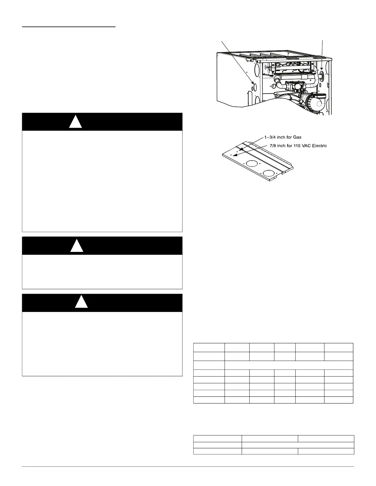
GAS PIPING
A11338
Fig. 30 – Gas Entry
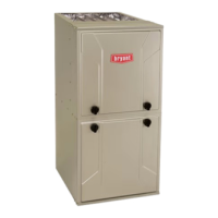
A230050
Fig. 31 – Alternate Gas and Electric Entry
NOTE: Top plate may be field drilled for alternate gas and 115 VAC
electric entry.
Gas piping must be installed in accordance with national and local
codes. Refer to current edition of NFPA 54/ANSI Z223.1 in the USA.
Refer to current edition of NSCNGPIC in Canada.
Installations must be made in accordance with all authorities having
jurisdiction. If possible, the gas supply line should be a separate line
running directly from meter to furnace.
NOTE: Use a back-up wrench on the inlet of the gas valve when
connecting the gas line to the gas valve.
The gas supply pressure shall be within the maximum and minimum
inlet supply pressures marked on the rating plate with the furnace
burners ON and OFF.
Refer to Table 11 for recommended gas pipe sizing. Risers must be used
to connect to furnace and to meter. Support all gas piping with
appropriate straps, hangers, etc. Use a minimum of one hanger every 6
ft. (2 M). Joint compound (pipe dope) should be applied sparingly and
only to male threads of joints. Pipe dope must be resistant to the action
of propane gas.
Table 11 – Maximum Capacity of Pipe
NOTE: Cubic ft. of natural gas per hr for gas pressures of 0.5 psig
(14-in. w.c.) or less and a pressure drop of 0.5-in. w.c. (based on a 0.60
specific gravity gas). Ref: Chapter 6 current edition of NFPA 54/ANSI
Z223.1.
WARNING
!
FIRE OR EXPLOSION HAZARD
Failure to follow this warning could result in personal injury, death,
and/or property damage.
Never purge a gas line into a combustion chamber. Never test for gas
leaks with an open flame. Use a commercially available soap solution
made specifically for the detection of leaks to check all connections. A
fire or explosion may result causing property damage, personal injury
or loss of life.
Use proper length of pipe to avoid stress on gas control manifold and
gas valve.
Gas valve inlet and/or inlet pipe must remain capped until gas supply
line is permanently installed to protect the valve from moisture and
debris. Also, install a sediment trap in the gas supply piping at the inlet
to the gas valve.
CAUTION
!
FURNACE DAMAGE HAZARD
Failure to follow this caution may result in furnace damage.
Connect gas pipe to furnace using a backup wrench to avoid damaging
gas controls and burner misalignment.
NOTICE
!
In the state of Massachusetts:
1. Gas supply connections MUST be performed by a licensed plumber
or gas fitter.
2. When flexible connectors are used, the maximum length shall not
exceed 36 in. (915 mm).
3. When lever handle type manual equipment shutoff valves are used,
they shall be T-handle valves.
4. The use of copper tubing for gas piping is NOT approved by the state
of Massachusetts.
Nominal: 1/2 (12.7) 3/4 (19.0) 1 (25.4) 1-1/4 (31.8) 1-1/2 (38.1)
Actual ID: 0.622 0.824 1.049 1.380 1.610
Length (ft) Capacity in Cubic Feet of Gravity
10 (3.0)
172 360 678 1390 2090
20 (6.0)
118 247 466 957 1430
30 (9.1)
95 199 374 768 1150
40 (12.1)
81 170 320 657 985
50 (15.2)
72 151 284 583 873
Gas Pressure Natural (in. w.c.) Propane (in. w.c.)
Maximum 13.8
Minimum 4.5” 12”
Gas Pipe Grommet Required
For Direct Vent Applications
Left Side Gas Entry. Gas Pipe
Grommet Required For Direct
Vent Applications.