bea5voltlogiclevel,shouldbe≥2.5Vdcand≤10Vdc.Thetipofthephonejackispositive(+)andtheringis
negative(-).
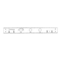
LED STATUS INDICATORS
CLIPPING: ThisLED(lightemittingdiode)willflashREDwhentheoutputwaveformisclippedindicatingan
overloadcondition.
MUTE: LightsREDtoindicatetheoutputsaremuted..
POWER: GREENindicatesnormaloperation
REDindicatesStandby
BlinkingRED/GREENafaultorthermaloverloadproblemintheunit.
ANALOG4Aux2 / DIGITAL4Select:
InB100-DAmodels:whenthisLEDisilluminatedgreenconcurrentlywitheitherD1, D2, D3
or D4 LEDs,itindicatesthatthedigitalinputsD1 (SPDIF),D2 (SPDIF), D3(TOSLINK)orD4
(TOSLINK) havebeenselected.
InB100&B100-Pmodels:whenilluminatedgreenthisLEDindicatesthatthelinelevelana-
logaudioinputAUX-2hasbeenselected.
AUX1, CD, TUNER, TV/SAT VIDEO & RECORD:
OneoftheseinputsourceLEDswilllightgreentoIndicatetheactiveinput.Indigitalmode
theseLEDswilllightREDifthe bitstreamiseitherabsentorunacceptable.
BALANCE Whentheleft/rightsignalbalanceisbeingshiftedoneoftheseLEDswilllighttoindicate
whichchannelisbeingattenuated.Balancecanbeadjustedin1dBincrementstoupto
-6dBineitherdirection. Stepping past -6dB in either direction will mute that channel fully
and the LED for that channel will turn red.
WhenbothLEDsareon(red),PASSTHROUGHmodeisindicated. (See “Pass Through
Mode” on page 4)
Note: InsomemarketstheLEDindicators,whicharenormallyred/green,maybered/blueinstead.When
red/blueLEDsaresuppliedgreenisreplacedwithblueandorangeisreplacedwithmagentainthe
abovedescriptions.
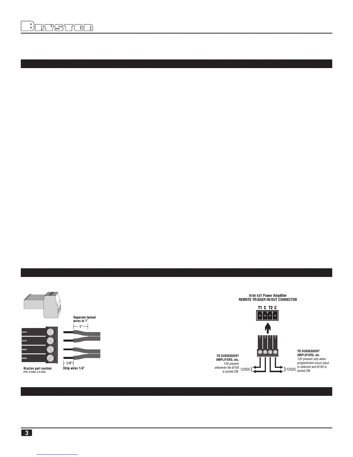
REMOTE POWER CONTROL ~ 12 VOLT TRIGGER CONNECTOR
Twotriggeroutputsareprovided.A12VdcsignalisplacedacrosstheT1andCpinsofthe12V TRIGGERScon-
nectorwhenevertheunitisfullypoweredup.Thentheunitgoesintostandbythisvoltageisremoved.
A12Vdcsignalwillbeplacedacross
the other pair of 12V TRIGGER output
pins (T2) whenever a certain user
programmedinput isselected asthe
sourceinput(seebelowforprogram-
ming instructions). When any other
input source is selected the 12Vdc
control voltage will be removed from
thesepins.PleasenotethatCmeans
“common” here and both C pins are
electricallyconnectedandidentical.
PROGRAMMING THE “T2” 12V TRIGGER OUTPUT
BydefaulttheT2triggeredoutputisinactive.Toprogramthisoutputtobecomeactive,whereuponacon-
trolvoltageof12VdcwillappearacrossT2&Cterminalswheneveraspecificsourceisselected,usethe
handheldremotecontrolasfollows:
•SelectthesourcethatyouwanttocoincidewithT2goingactive.