Description 1
12
ekr 500 web guiding controller EDV No.: MD.299.01.06 Chapter: 1
with removable control panel Date: 29.07.08 Page: 6/86
1.5 Terms used
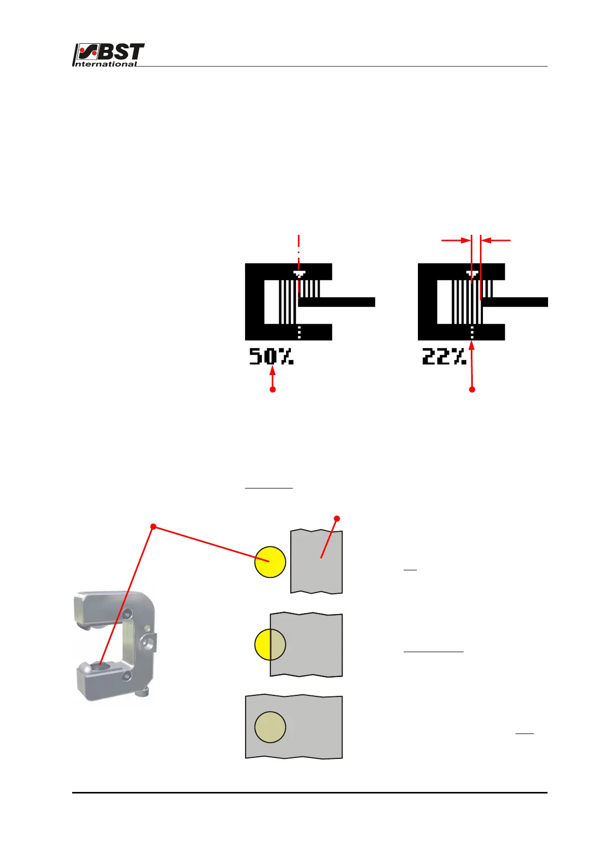
1.5.1 Set position
The set position is the required position for the web of material in
the sensor scanning area. It can be set up in “Automatic“ mode
using the control panel arrow keys (see chapter 7.4).
The set position setting will be marked on the control panel display
by a white triangle being superimposed around the sensor symbol.
The relative coverage of the sensor scanning area will be
displayed as a percentage beneath the sensor symbol.
Examples:
0% covering
No
material within
the sensor scanning area.
50% covering
Only one half
of the sensor
scanning area is covered.
100% covering
Sensor scanning area is fully
covered.
Deviation between
set and actual position
Set position = Actual position
Center of
sensor scanning area
Relative coverage of the
sensor scanning area
Sensor scanning area
Web of material

 Loading...