Description 1
12
ekr 500 web guiding controller EDV No.: MD.299.01.06 Chapter: 1
with removable control panel Date: 29.07.08 Page: 7/86
1.5.2 Sensor 1 / Sensor 2
In this operating manual, the sensors that are connected to the
controller are designated with “sensor 1“ and “sensor 2“.
According to the BST definition, the following link applies between
the selection buttons for the guiding mode and the sensors:
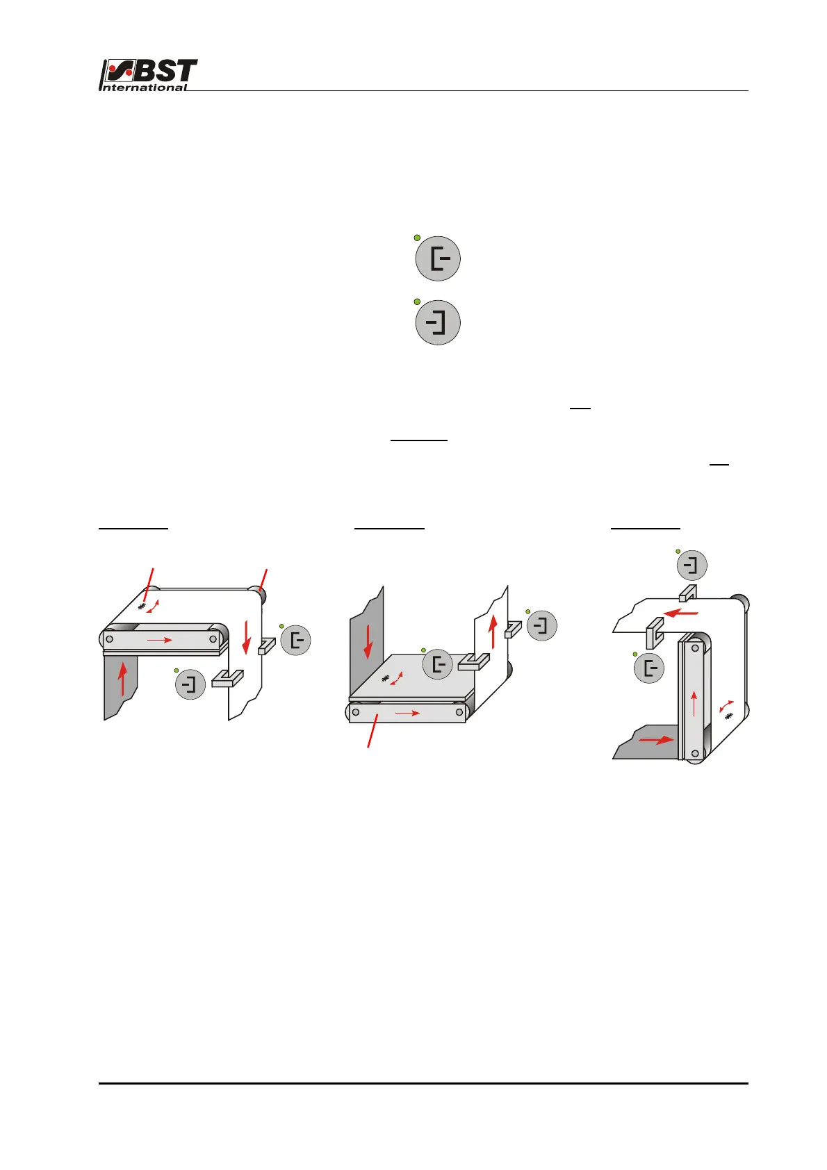
= Sensor 1 (left web edge)
= Sensor 2 (right web edge)
The following is valid in respect of the sensor mounting positions:
The sensor, which is located to the left
of the material in the
web running direction (when looking from the material top
side), is sensor 1
.
The material top side is the side of the material web which is not
in
direct contact with the deflection pulleys of the guiding device.
Example 1:
Example 2: Example 3:
As standard, sensor 1 must be connected to terminal strip X1,
while sensor 2 must be connected to terminal strip X2 of the
controller (see terminal assignments, chapter 5.5).
Sensor 1
Sensor 2
Sensor 1
Sensor 2
Sensor 1
Sensor 2
Pivot
Deflection pulley
Guiding device

 Loading...