Index I
1
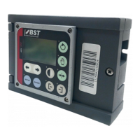
ekr 500 web guiding controller EDV No.: MD.299.01.06 Chapter: I
with removable control panel Date: 29.07.08 Page: 1/2
Index
Actuator
Determine sense of motor rotation...................... 45
Maintenance ....................................................... 85
Operation in generator mode .............................. 44
Selection of the used actuator ............................ 40
Servo-center position EMS 17/21/22 ............ 49, 51
Software limit switches EMS 17/21/22.... 49, 51, 56
Start-up ............................................................... 44
Stroke limitation EMS 17/21/22..................... 49, 51
Technical Data.................................................... 19
Ambient conditions .......................................... 22
ATEX ......................................................... 10, 22
Automatic guiding ............................................ 68
Bright value...................................................... 61
Bus connection fault ........................................ 59
Bus status........................................................ 42
Cable connections ............................... 10, 31, 84
Cable extension........................................... 4, 26
Center positioning............................................ 68
Connectable components.................................. 5
Control panel ................................................. 4, 8
Ambient conditions ............................................. 16
Assembly ............................................................ 26
Cable guide......................................................... 25
Connecting cable .................................................. 4
Control console mounting ............................. 26, 29
Dimensions ......................................................... 17
Display................................................................ 16
Installation cut-out............................................... 29
Installation kit ...................................................... 29
Installation versions ............................................ 26
Key functions ........................................................ 9
Maintenance ....................................................... 84
Mounting plan ..................................................... 27
Plug assignments ............................................... 39
Power supply ...................................................... 16
Protection class .................................................. 16
Securing kit ......................................................... 26
Set device address ............................................. 76
Technical data .................................................... 16
Terminating resistor ............................................ 78
Turning the control panel .................................... 25
Wall mounting ............................................... 26, 27
Weight................................................................. 16
Controller ........................................................... 4
Ambient conditions ............................................. 13
Analogue inputs .................................................. 14
Assembly ............................................................ 23
Control panel interface........................................ 15
Digital inputs ....................................................... 14
Dimensions ......................................................... 17
LEDs ................................................................... 42
Maintenance ....................................................... 84
Mounting ............................................................. 24
Mounting plan ..................................................... 23
Output fault relay................................................. 14
Output motor output stage .................................. 14
Plug assignments................................................ 38
Power supply ...................................................... 13
Processor board.................................................. 33
Protection class................................................... 13
Service indications .............................................. 42
Set device address ............................................. 75
Space needed to open the enclosure cover........ 23
Technical data .................................................... 13
Terminal assignment..................................... 34, 35
Terminal strips .................................................... 34
Terminating resistor ............................................ 77
Weight................................................................. 15
Controller gain
Adjustment of gain .............................................. 53
Controller interlock .......................................... 58
Dark value ....................................................... 61
Decommissioning ............................................ 86
Default settings.......................................... 75, 79
Generate default settings.................................... 79
Device addresses............................................ 75
Device status................................................... 42
DIL switches .................................................... 40
DIL switch S4...................................................... 40
DIL switch S5...................................................... 41
Dimensions...................................................... 17
Display....................................................... 16, 55
Display of system information ......................... 72
EFE 1............................................................... 73
Start-up ............................................................... 54
EFE 1000 ........................................................ 73
Start-up ............................................................... 54
Electrical connection ....................................... 31
Electro static discharge ................................... 12
Electronic remote precision adjustment .......... 73
Start-up ............................................................... 54
EMC-wiring...................................................... 32
Emissions ........................................................ 12
ESD ................................................................. 12
ESD protection.................................................... 12
Factory settings ............................................... 75
Firmware
Display firmware version..................................... 72
Load firmware ....................................................... 2
Functional principle ........................................... 5

 Loading...