BTL-2000
USER'S MANUAL & USER’S GUIDE
Page 22 z 45
NOTE: The acupuncture attachment decreases probe aperture approximately 20% resulting in a reduced probe
output. The instrument automatically calculates this reduction and corrects the output to a preset laser beam
density.
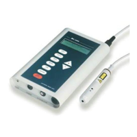
2. Acupuncture Set (not included in standard accesories)
This set contains acupuncture probe with spring-mounted needle, chrome-plated patient pin, and connection
cable. This connection cable consists of a connector on one end, identical to the connector of the laser probe
and on the other end two different color banana jacks. For measuring acupuncture points, initially connect the
connector cable end to Probe Output (2). Attach the reference chromium-plated electrode to the red banana
plug, which the patient will hold tight in his/her hand. Attach the acupuncture probe with needle to the green
banana plug. This probe contains a special spring that ensures good contact with the skin without using
excessive pressure. The instrument will then detect the acupuncture set and begin to measure skin resistance.
The resistance of the skin is measured using 0.5 V (600 kΩ). This level of generated electricity is directly
proportional to the resistance of the skin. The Bar graph displays skin resistance in %. As you begin to pass the
spring mounted needle over the skin, the acupuncture points are defined by a local decrease in voltage
resistance, therefore noticeable by an increased of frequency on the Bar graph and an increase in acoustic
tone. When the acupuncture point is located, disconnect the needle probe, replace it with the laser probe and
desired therapy can be started. The procedure of therapy is described in chapter “Performing therapy”.
A CUPUNCTURE
Pr o b e mod Auto
0 % % 30%
Press the [ + ] a [ - ] arrows to move between levels of instruments resistance sensitivity. The automatic mode
(AUTO) is then changed to (1), (2), (3) or (4). Setting (4) represents the most sensitive setting for patients with very
dry skin. Setting (1) represents the least sensitive setting for patients with very wet skin. Use the [ENTER] push
button to store new data. The therapy parameters will then be displayed:
D e n s . _0.9J/cm
2
F r e qu ency ConTinual
A r e a 1.0cm
2
Pwr 30mW
T i m e 1:39 REady
Press the [ + ] or [ - ] arrows to adjust therapy parameters. Press the [TAB] push button to move between therapy
parameters. Press the [ENTER] push button to store new data. After pressing the [ENTER] push button “Data
saved“ will be shown on display. Press the [ESC/STOP] push button to return to previous menu.
2.8.6 PROBE TEST: Optical Power of Probe
This function measures probe output and the status of the probe diode. BTL-2000 automatically tests the probe
performance and corrects the power for optimal output (only for the BTL probes).
The warning messages ATTENTION and LASER IRRADIATION will be displayed followed by the message PROBE
TEST. Probe parameters will be automatically displayed. Connect probe without cover to the TEST enter on the lower
panel of the instrument. Remove the brass cover and insert probe into laser optical power meter “TEST” (14). Using
probe push button to begin laser emmision. Display will show actual measured probe power, which is dependent on
the angle of the probe. Terminate laser emmision using probe push button.
PROBE TEST
T y p e 685nm/30mW
O u t put26mW