C−LRV lift control valve Product description
15/92
300−I−9010212−E−10/08.08
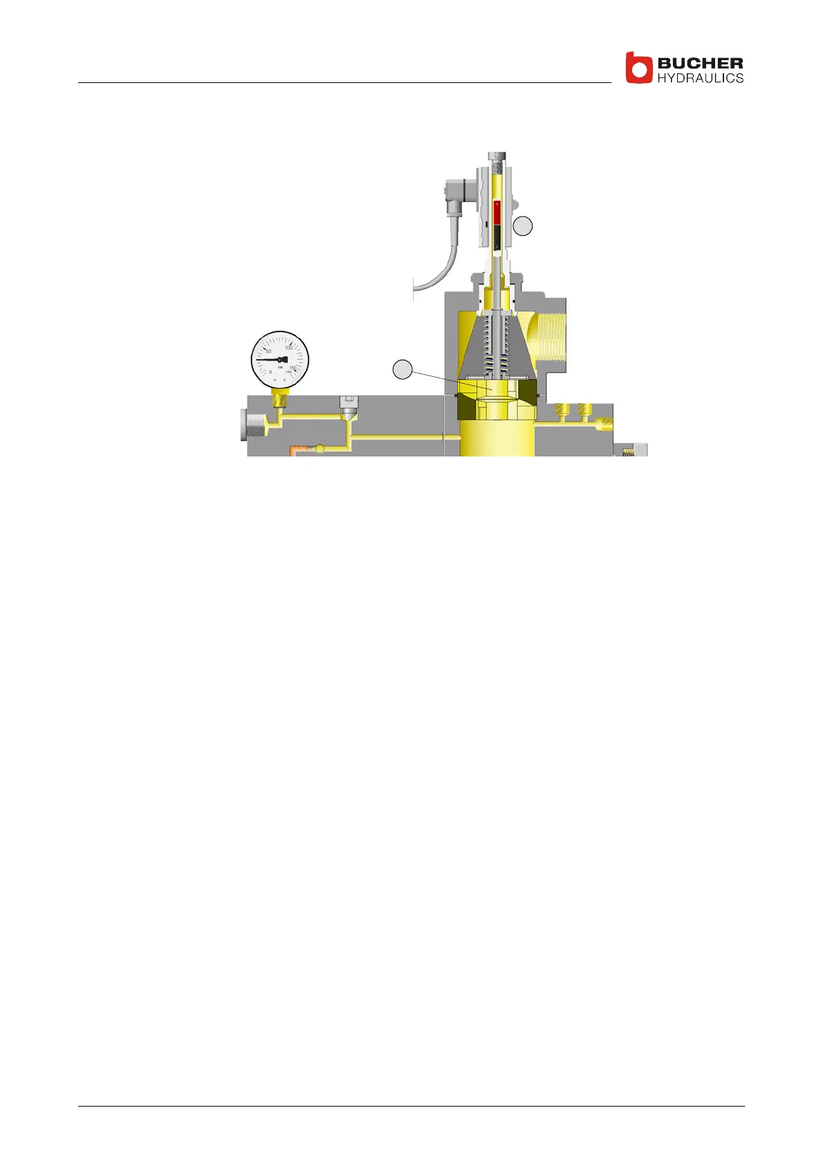
3. Flow−rate measuring system
10
12
S The oil flows through the flow meter (12) in both the up and down
directions
S The baffle−disc is displaced axially as a function of the flow rate
S This axial displacement is converted by a non−contacting feedback
transducer (10) into an electrical DC signal (the feedback signal),
which is then sent to the C−DELCON
S The output signal (the feedback) is proportional to the flow rate
S The controller in the C−DELCON works to match the feedback value
to the demand signal

 Loading...