C−LRV lift control valve Product description
12/92
300−I−9010212−E−10/08.08
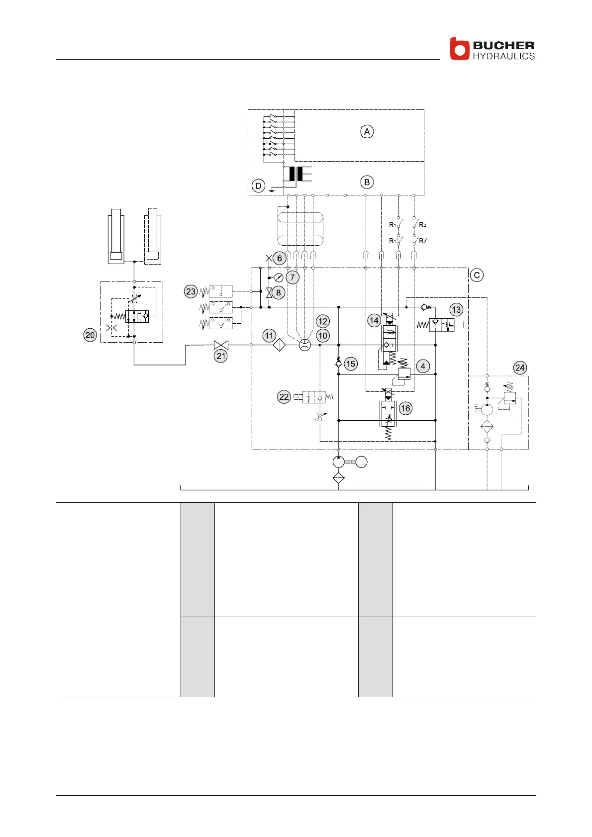
1.3.1 Simplified hydraulic–electrical diagram
M
Legend 4
6
7
8
10
11
12
13
Pressure−relief valve
Test point, G½
Pressure gauge
Pressure gauge shut−off screw
Feedback sensor
(non−contacting)
Main filter
Flow−rate measuring system
Emergency−lowering valve
14
15
16
20
21
22
23
24
DOWN spool
Check valve
UP spool
Pipe−rupture valve
Ball valve
Electrical emergency−lowering
valve (optional)
Pressure switch
Hand pump
Z1
Z2
Z3
P
T
Z
Pressure switch port
Pressure switch port
Hand pump port
Pump port
Tank port
Cylinder port
R
1
R
2
A
B
C
D
to EN81−2, 12.4.1/12.4.2
to EN81−2, 12.4.1/12.4.2
C−DELCON
NTA−2
C−LRV
Control cabinet (customer’s)
 Loading...
