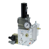
C−LRV lift control valve Product description
30/92
300−I−9010212−E−10/08.08
Terminal Description
Control signals
1
2
3
4
5
21
22
23
12
12
6a
7
6b
8
K1 Fast UP
K2 Slow UP
K3 Fast DOWN
K4 Slow DOWN
K5 Inspection speed
K6 Speed reduction (auxiliary speed)
K7 Speed reduction (auxiliary speed)
K8 Speed reduction (auxiliary speed)
Ground/reference potential (GND) for command inputs (K1...K8)
Ground/reference potential (GND) for command inputs (K1...K8)
Common, DOWN solenoid
Output, DOWN solenoid
Common, UP solenoid
Output, UP solenoid
Demand / feedback monitoring
17a
18
17b
SIU−1 (demand/feedback monitoring), SIU−4 (v ≤0.3m/s)
⇒ 1.5.1
Connection for feedback cable
9
10
11
12
Stabilised voltage supply +15V
Feedback signal (input)
Stabilised voltage supply −15V
Ground, Hall−effect sensor (GND)
Emergency power supply
19
12
20
+24V emergency power supply
Ground, emergency power supply (GND)
−24V emergency power supply

 Loading...