5 Putting into operation
35 R-210/215 Operation Manual, Version B
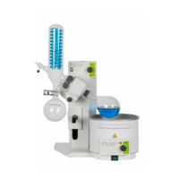
5.4 Glass assembly
To install the glass assembly, consider the following:
To fasten the fl anges you do not have to remove the fl ange screwed connection (position in Fig.
5.3). Just open the fl ange screwed connection wide enough, so that the fl ange can be pushed
through.
You can also secure the glass assemblies V, S, C, E, CR, BY using the corresponding optional
support rod.
Secure the receiving fl ask with the clip provided for this purpose.
ATTENTION
Check the glassware for damages prior to each operation and use only glassware that is in perfect
condition. Glassware with cracks, stars or other damages can break during operation.
NOTE
To achieve optimum tightness of the system, all joints on the condenser side must be greased.
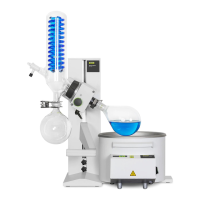
5.5 Installing the condenser and the seal
1
2
3
4
5
When installing the condenser and mounting the
seal, consider the following order:
Insert the vapor duct until a click sound is
heard.
Fix the seal to the condenser .
Screw on the condenser with the fl ange
screwed connection (normally, the fl ange
screwed connection must not be removed)
Screw the Combi Clip onto the vapor duct.
•
•
•
•
Fig. 5.5: Exploded view of condenser and seal
•
•
•