Instruction Manual
12
06/23
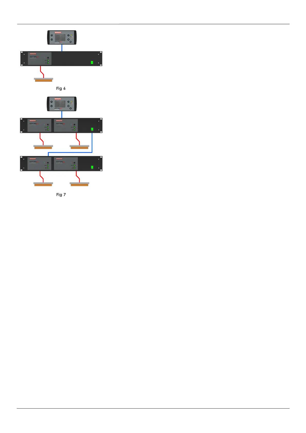
Use of a Command+ module,
(6002-1000)
permits the remote
management of a DCCT output stage, in this example a Single
Channel Output Unit
(6002-0101)
is used, and this offers the same
capabilities as the Integral Single Channel unit described above.
The controller and the output stage(s) have interlock inputs, and the
interface capability to drive alarms / paint markers / etc. The
network cable may be up to 100m long. See Fig 6.
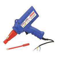
In this final example, the network arrangement permits the remote
control of two Dual Channel Output Modules
(6002-0102)
It is possible to construct a remotely managed network with one,
two, three or four output channels.
Whilst the output voltage and alarm threshold are identical for all
channels, the controller and the output stages are provided with
independent fault counters, and individual interface capability to
drive alarms / paint markers / etc. See Fig 7.
Electrodes
A wide range of rollers, metallic or carbon fibre brushes, conductive rubber, metallic gauze or mesh
can be used to form electrodes. Ideally, the electrodes will be in contact with the material being
tested. If this is not possible then any airgap between the material and electrodes should be minimised.
Of course, it is important that the electrodes do not damage the material being tested, so the form and
material used for their construction should be chosen with this in mind. It is also likely that the surface of
these electrodes will be damaged over time, so functional parts, such as cores for mould tools, should
not be used in this way.
In cable-testing applications, the ground electrode is normally formed by the core (or cores) of the
cable itself, and arrangements must be made to ensure a low resistance path from the cable core to
the instrument, either in the supply, or take-up reel. Similarly in pipe insulation testing, a ground
connection to the metal tube itself will be necessary. This may be arranged by means of a travelling
contact, or a static brush, which is able to make contact with the tube as it passes through the HV
electrode assembly.
It is recommended that the HV cable length between instrument output and electrode should always
be minimised, and it is most important not to exceed 2m of armoured cable.
Buckleys has considerable experience in the design and manufacture of HV and Grounding electrodes
and we are happy to advise, and to quote for custom installations including extrusion of films and
membranes, and a wide range of coated components including wires, cables and flexible and rigid
pipes.