06/23
7
Overview
High voltage pinhole detection has been commonplace for nearly half a century. The principle of such
testing is that the material being tested has a greater breakdown voltage (in kilovolts) than the
equivalent “thickness” of air, and this resistance to breakdown prevents current flowing between
electrodes placed either side of the material being tested.
If there is a flaw or fault in the material being tested (which may be a microscopic hole, or one so large
that it is easily visible, or a significant reduction in thickness even without a hole) a current will pass,
either as a spark which may be audible and visible, or as an ionisation current which is unlikely to be
visible. Buckleys High Voltage test equipment incorporates detection circuits which will detect the flaw
in either case. Sparks will always be detected. Ionisation currents will be detected providing they
exceed the user-defined current threshold.
Therefore, there are two electrodes – the first will be connected to the High Voltage (HV) output of the
instrument, and the second to the ground connection. This second, ground electrode may also be
connected to grounding points for the installation and/or building.
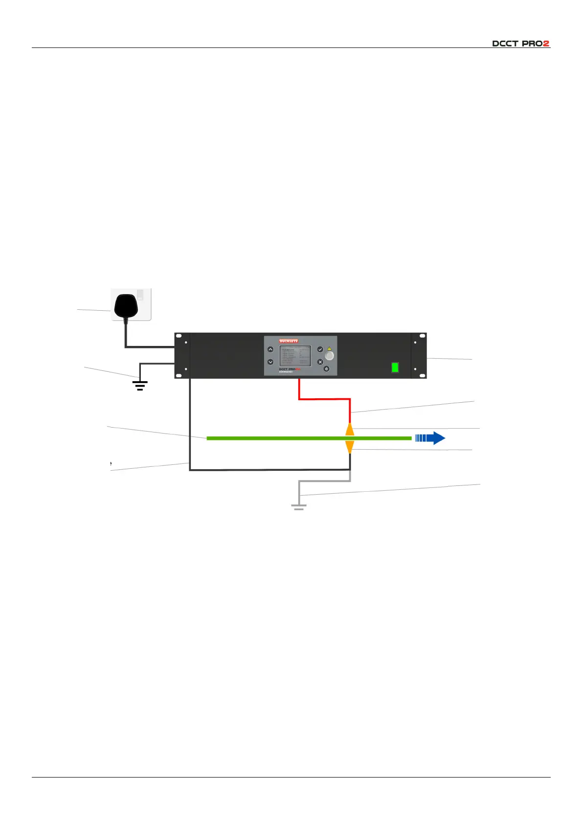
Fig 1 – A typical DCCT installation.
As shown in Fig 1, it is necessary to arrange the test electrodes so that the material passes between
them, and ideally the electrodes should always be in contact with the material. If this is not possible, it is
beneficial to minimise the air gap between electrodes and material as much as possible.
Buckleys DCCT instruments are purpose designed, based on over forty years’ production of HV Non-
Destructive Test (NDT) equipment for industry. The instrument provides a highly stable user-controlled
HV DC output, from 0.9-40kV, and an adjustable sensitivity alarm whose threshold may be set between
10 and 450µA. Both may be easily adjusted by the user, and the settings can be locked by means of a
manager-defined passcode.
Additionally, these instruments are fitted with software-controlled zero-volt relay connections which
operate in synchronisation with the alarm, allowing interconnection with PLC controllers, or a variety of
other devices, such as a paint spray for marking. Additionally, the instrument is fitted with interlock
connections allowing the HV output to be remotely controlled and disabled, should the safety case
require it. There is also a fault counter.
Mains
Supply
90-250V AC
Instrument
Ground
Material to be
tested, being
drawn between
electrodes.
Ground Electrode
connection to
Instrument
DCCT Instrument
HV Connection
HV Electrode
Ground Electrode
Optional Local
Ground
Connection