06/23
17
Setup (continued)
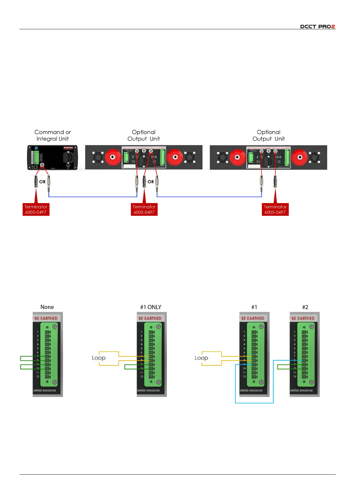
Network Cable Connection
The network provides a low voltage connection between instruments, as shown in the diagrams on
page 11 above. The network requires a terminator plug
(6005-0497)
which is supplied with all Integral and
Command+ units. If your installation does not require a network, align and insert the plug into the
integral unit. The plug fits by a straight
PUSH
, and is removed by a straight
PULL
; do NOT twist.
If you are connecting multiple instruments, the network cables must be daisy-chained – a cable from
the command unit to the first output unit, and from the first to the second output unit if applicable. The
terminator should be fitted to the remaining socket in the last unit.
Fig 12 – Network Connections
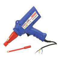
Interlock Loop Connection
Buckleys always recommends that HV electrodes should be installed in an area from which staff are
excluded when they are energised. This is particularly important where the Command+ module is used,
and it may not be possible to verify visually that the area is safe before energising HV. To facilitate this,
the instruments are provided with interlock connections which will disable the HV generator if the loop is
not closed. This loop can be connected to door switches or guarding. The precise connections
depend on whether one, or two modules are used:
Fig 13 – Interlock Loop Connections