Instruction Manual
18
06/23
Remote HV Energise Connection
Many existing customers use a DCCT connected via an HV cable to a passive HV handle. This handle is
fitted with an
ON
button to enable HV generation, and the facility to connect such a handle is
provided for with the Integral Pro2 versions of the instrument.
Integral Instruments are fitted with a remote-control connection which allows
a handle button or other remote switch to control the generation of HV. An
adaptor
(5700-1076 / 6005-0496)
is available to connect a Buckleys DCCT handle
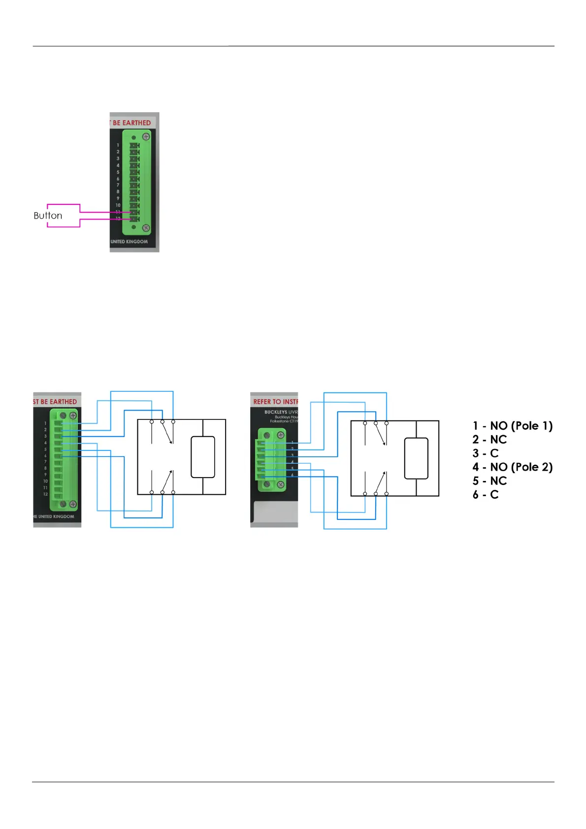
to the necessary connections on the rear of the instrument. The remote-
control button should be connected between pins 11 & 12 of the green 12-
way connector.
Buckleys do not recommend the use of a latching switch or button in this
application.
A remote-button handle should not be used in multi-channel applications.
Fig 14 – Remote Switch Connections
Alarm Relay Connections
Within each output channel of the DCCT instruments, a dual-pole, dual-throw relay is fitted. The relay
contacts are zero-volt; there is no electrical connection to them within the instrument. The contacts are
rated at 250V & 5A.
The contacts are pins 1-6 of the 12-way connector on all units. In the case of dual channel instruments,
the second channel has a dedicated connector for its independent relay. Relay pins are as tabulated.
Fig 15 – Alarm Relay Connections