Operations
POWERmini USB User Guide 8 2.0
Status Page
The Status page is where important information about the system is shown.
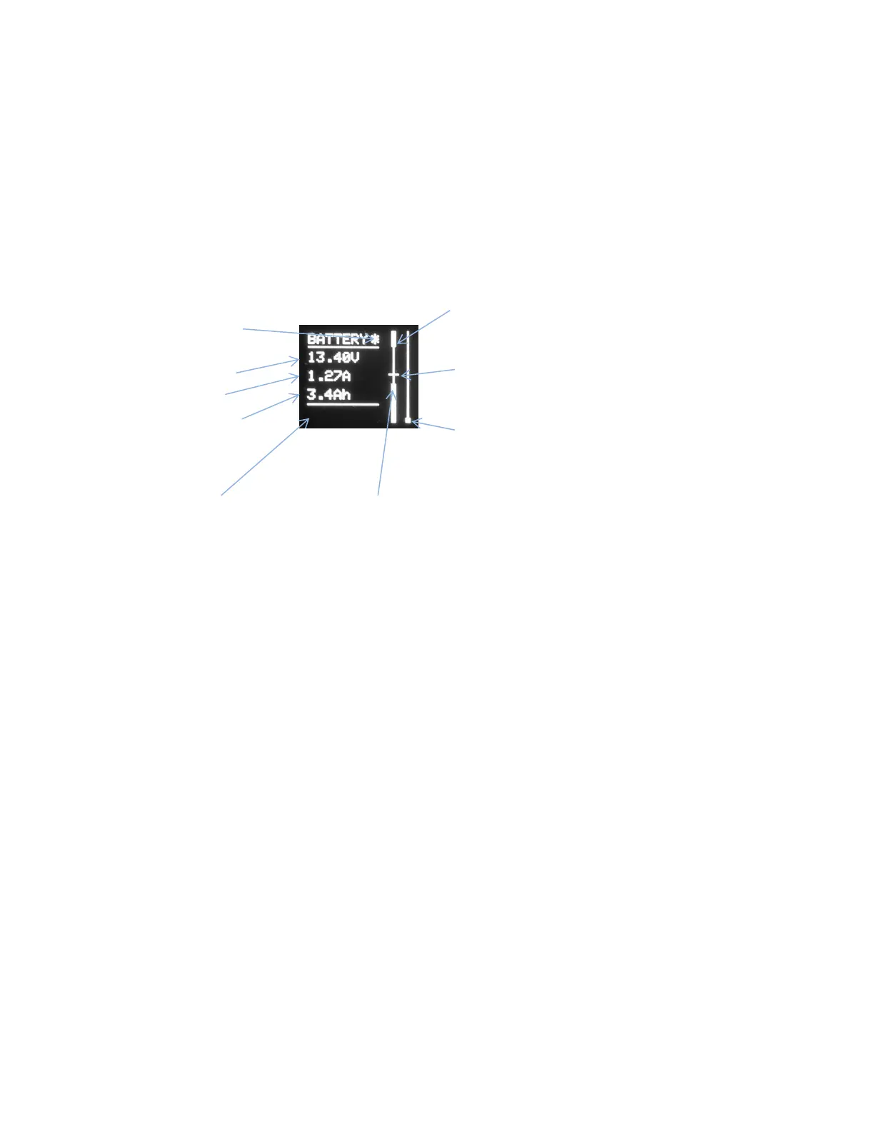
The left side of the Status page provides digital information about the battery including battery voltage,
load current and the amount of charge that has been provided by the battery to the load since power has
been applied. The status of the audible alarm is also indicated here. When the alarm is enabled an asterisk
is displayed to the right of the “BATTERY” title line. The asterisk is not shown when the audible alarm is
disabled.
Two vertical bars to the right of the digital information provide a graphical view of the state of the battery
and the user defined settings (see Figure 4).
Battery voltage marker
The vertical position of the marker is from 10V
to 16V (illustration shows 13.40V).
Load current
The height of the bar graph indicates the
instantaneous current flowing to the load (full
scale =35A).
The upper and lower threshold disconnect limits are shown on the left vertical bar as the thick bars at the
top and bottom of the graph. The thin vertical line between them shows the useful region of battery
voltage. The thin horizontal marker indicates the instantaneous battery voltage.
As the battery voltage decreases the battery voltage marker will move down the scale towards the white
box representing the low voltage disconnect limit (LVD). When the marker is about 0.5V above the LVD a
Low Voltage Warning message is displayed in the space at the bottom left of the display, the front panel
POWER LED will flash red and the audible alarm (if enabled) will sound.
As the battery discharges further, the battery voltage marker will reach the lower voltage limit and the
Shutdown Warning message will be displayed at the bottom of the display. If the automatic shutoff
feature is enabled, power will be disconnected 10 seconds after this point has been reached. The solar
charger will continue to work if the battery voltage is above 10.0V. The output will be reconnected when
the battery voltage rises above the low voltage reconnect limit. This is a user defined value. See
Threshold Voltages on page 10 for information on how to set the Low Voltage Reconnect threshold
voltage.
If the battery voltage increases above the lower edge of the high voltage limit box, the unit will
automatically disconnect the load to protect your radio equipment. Power will not be restored until the
voltage falls below the user defined reconnect threshold. See Threshold Voltages on page 10 for
information on how to set the High Voltage Reconnect threshold.