Initial start-up2
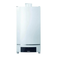
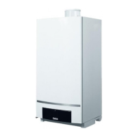
Wall-mounted condensing gas boiler Buderus 800 - Subject to modifications resulting from technical improvements!
28
Setting the heating capacity
Open the cover of second control level (fig. 31, item
7).
Set the heating capacity in accordance with the re-
quired heat demand (table 8) on the controller
(fig. 31, item 6). Take into account the appropriate
losses caused by the flue gas system (table 9).
Setting the pump over-run time
Move the switch
( (fig. 31, item 4) to position "1".
Pump over-run time 4 minutes.
Move the switch
( to position "2" when the system is
controlled in accordance with the room temperature
and if parts of the system outside the detection area
of the room temperature controller are at risk of freez-
ing (e.g. radiators in the garage).
Pump over-run time 24 hours (constant operation).
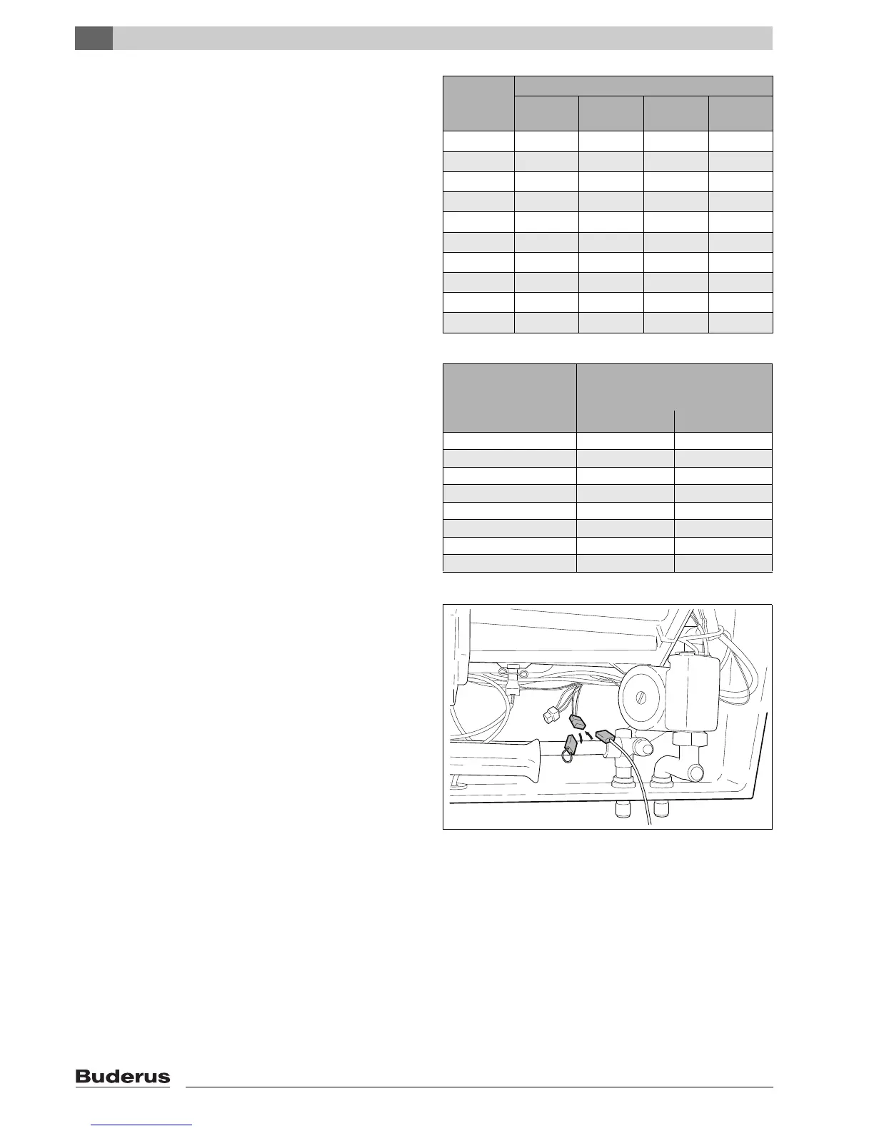
Connecting the hot water sensor FW
Remove the bridge plug (fig. 32, item 1).
Cable colours: black/white and lilac.
Connect 3-m long extension cable (fig. 32, item 2) for
the hot water sensor to the plug and fit sensor in the
reservoir.
Con-trol-
ler posi-
tion
Heating capacity in kW (±5 %)
800-24
24T25
800-29
29T25
800-43 800-60
1 6.6 8.4 12.1 22.0
2 8.4 10.8 15.2 25.3
3 10.2 13.0 18.3 29.7
4 11.9 15.2 21.4 33.5
5 13.6 17.5 24.5 37.3
6 15.3 19.7 27.7 41.2
7 17.0 21.9 30.8 45.0
8 18.7 24.1 35.9 48.8
9 20.4 26.3 37.0 52.7
10 22.0 28.0 40.2 56.5
table 8 Heating capacity
Pressure loss of
flue gas system
in Pa
Available portion of
maximum capacity
in %
800-24/29/43 800-60
20 98.5 98.5
30 97.8 98.0
40 97.1 97.4
50 96.4 96.9
60 95.6 96.3
70 94.8 95.8
80 – 95.2
90 – 94.7
table 9 Capacity losses
fig. 32 Hot water sensor FW for external storage-type water
heater
1
2