Initial start-up 2
Wall-mounted condensing gas boiler Buderus 800 - Subject to modifications resulting from technical improvements!
29
type 800 – 24T25 H/V and 800 – 29T25 H/V
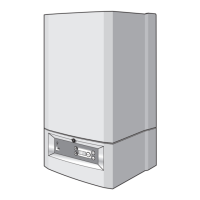
Setting the hot water flow limiter
Set the desired value on the flow volume limiter
(fig. 33), e.g. for 60 °C at 6 liters/min for type 800 –
24T25 or 8 liters/min for type 800 – 29T25.
2.2.3 Measuring the gas supply pressure (flow pressure)
Open at least one radiator thermostat valve.
The gas boiler must not be turned on yet.
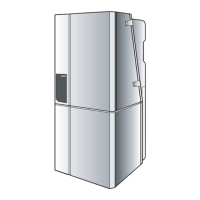
Move the chimney sweeper switch (fig. 34) to posi-
tion "1".
On type 800 – 60 the full capacity is achieved after
approx. one minute. Therefore measurements
should be carried within one minute of boiler opera-
tion.
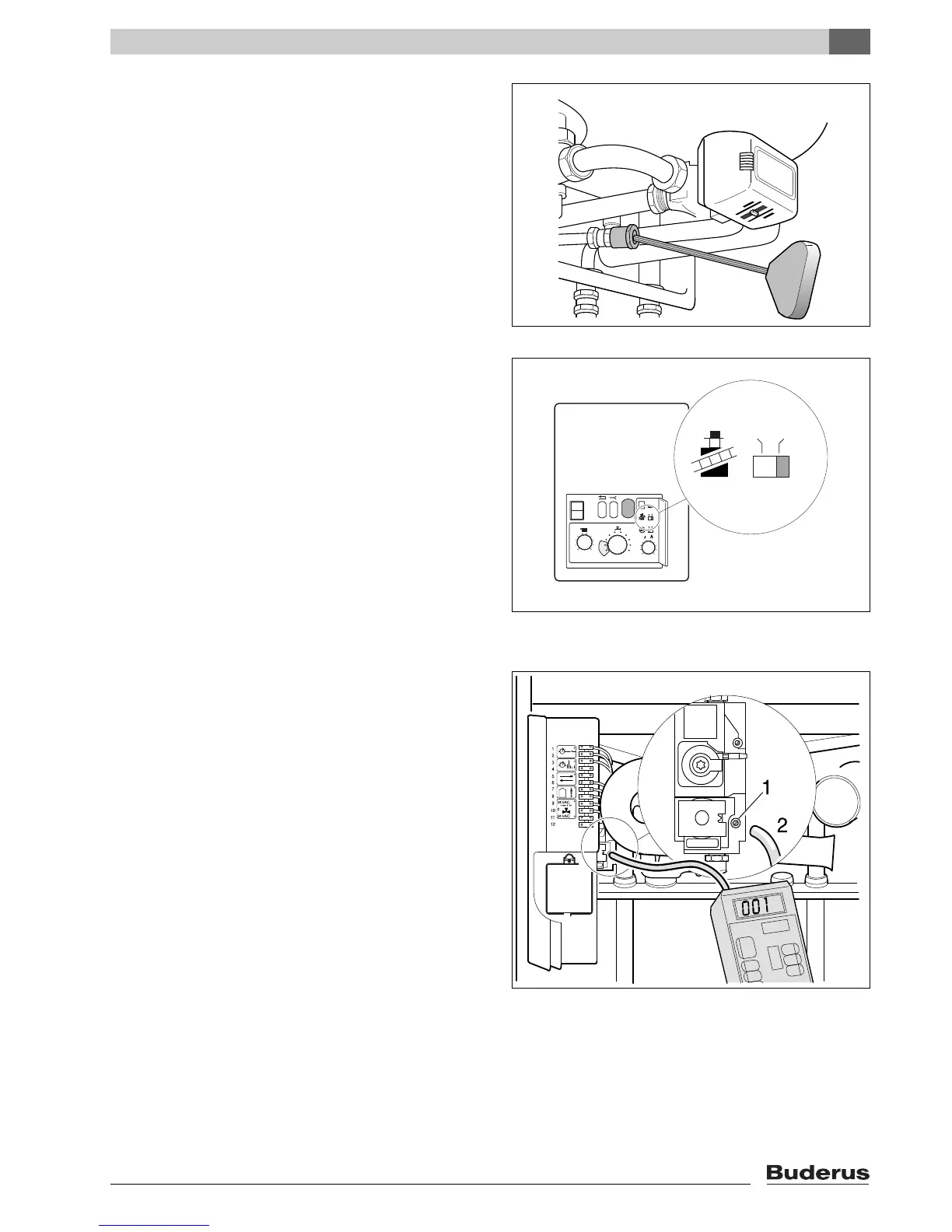
Loosen the screw plug on the gas distribution pres-
sure test nipple on Honeywell gas units (fig. 35,
item 1) two turns, fully unscrew the plug on SIT gas
units (fig. 36, item 1).
Fit the measuring hose of the pressure gauge to the
test nipple (fig. 35, item 2 or fig. 36, item 2).
Slowly open the gas service valve.
Insert the mains plug and move the mains switch to
"I". After about 30 seconds the burner will fire.
Measure the gas distribution pressure and enter into
the certificate.
The gas distribution pressure must be
min. 17 mbar, max. 25 mbar, rated distribution
pressure 20 mbar for natural gas H and
min. 30 mbar, max. 50 mbar, rated distribution
pressure 37 mbar for LPG.
Pull off the measuring hose and tighten up the screw
plug on the test nipple.
fig. 33 Hot water flow volume limiter
Turning to the right = reducing the flow volume
Turning to the left = increasing the flow volume
fig. 34 Chimney sweeper switch