Servicing 5
Wall-mounted condensing gas boiler Buderus 800 - Subject to modifications resulting from technical improvements!
53
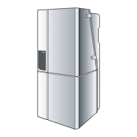
5.3.10 Replacing the flow, return and safety sensors
Close maintenance isolating valves.
Drain the 800 Series.
Unplug.
Unscrew sensor and replace with new unit.
Plug in cable connection.
Open maintenance isolating valves.
table 10 Resistance values (indicative values) of the sensors
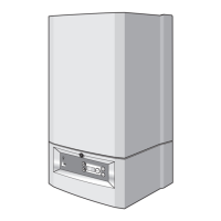
fig. 66 Checking the mains-water sensor
fig. 67 Replacing the flow/return sensors
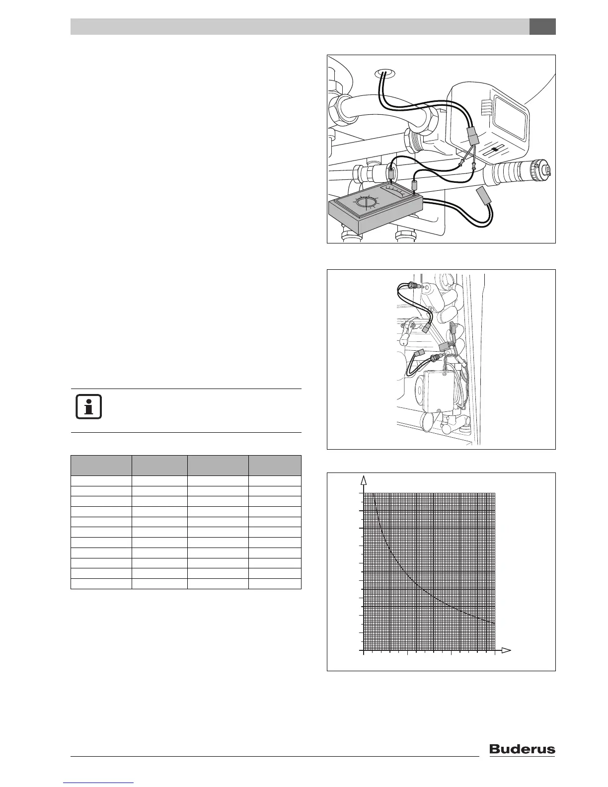
fig. 68 Boiler temperature sensor diagram
Boiler temperature sensor
(˚C)
R (Ω)
40
50
60
70
80
90
0
0
10
20
30
10,0005,000 15,000
NOTE
Fill the 800 Series and purge the system of
air.
Temperature
in °C
Resistance
in
Temperature
in °C
Resistance
in
0 29,490
5 23,462 55 3,271
10 18,787 60 2,760
15 15,136 65 2,339
20 12,268 70 1,990
25 10,000 75 1,700
30 8,197 80 1,458
35 6,754 85 1,255
40 5,594 90 1,084
45 4,656 95 1,940
50 3,893 100 1,817