Servicing5
Wall-mounted condensing gas boiler Buderus 800 - Subject to modifications resulting from technical improvements!
60
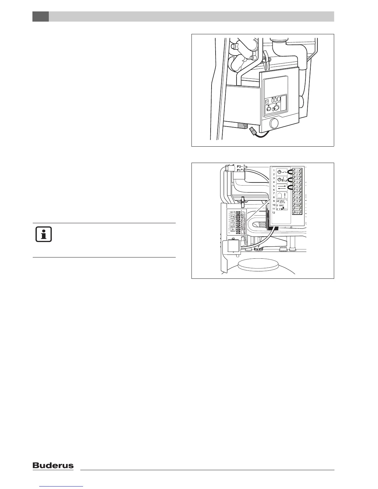
5.3.21 Checking the wiring connection to the KIM
Disconnect the system from the power supply.
Check plugs and wiring connections to KIM
Connect system to mains power supply.
5.3.22 Checking the controller connections at the boiler
Set the mains switch to “0”.
Remove loop (non-conductive) from terminals 1
and 2.
Loosen cable at terminals 3 and 4.
Fit a link between terminals 1 and 2, 3 and 4.
Set the mains switch to “I” and press “reset”.
If the 800 Series goes into standby mode after start-
up
(display 0 H), the room-temperature control device is
defective.
Move mains power switch to “0”.
If the room-temperature control device is in order,
remove the bridging leads and attach the cable and
(non-conducting) link.
5.3.23 Replacing the room-temperature control device
Loosen all cables. Note order of cable terminals.
Attach cables, in the right order, to the new room-
temperature control device.
Carry out the corresponding adjustment settings on
the
room-temperature control device.
fig. 83 Checking the wiring connection to the KIM
fig. 84 Checking the controller connections at the boiler
NOTE
The system is delivered ready-fitted with a
non-conductive link between terminals
1 and 2.