Installation (for engineers only)
Logamatic SC40 - Technical specifications are subject to change without prior notice.
12
4
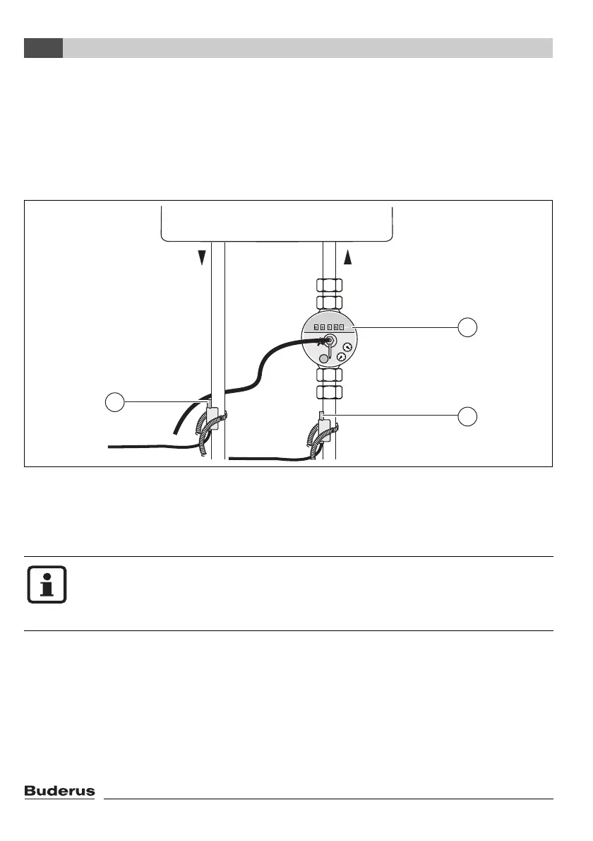
V Fit volumetric flow meter below the solar pumping station in the solar return pipe (Æ Fig. 7,
item 1). Pay attention to direction of flow and fitted position (meter dial must not face down-
wards).
V Fix temperature sensor for solar return (Æ Fig. 7, item 2) in position. For details of temperature
sensor fixing, refer to page 10, Fig. 5.
V Fix temperature sensor for solar flow (Æ Fig. 7, item 3) in position. For details of temperature sen-
sor fixing, refer to page 10, Fig. 5.
Fig. 7 Fitting the volumetric flow meter and temperature sensors
1 Volumetric flow meter
2 Return temperature sensor
3 Flow temperature sensor
V Wire up electrical connections as shown in Section 4.4.
The heat meter is used only to check system function. It is not capable of metering to
EN 1434 or determining yield. Calculation of yield requires a device with a calibration
certificate, usage data (water volume, room heating heat requirement), weather data
and system simulation.
7747006072-34.1 SD
1
2
3
 Loading...
