6
Placing the heating system in operation
Logano G234X – 6 720 804 886 (2012/08)20
10. Check the supply gas pressure while the boiler is operating. The
connection pressure for natural gas must be between 7 and 10.5
inches W.C. (17.4 to 26.2 mbar) and between 11 and 13 inches W.C.
for propane gas (27.4 to 32.4 mbar). Record the values measured in
the commissioning log ( page 22).
11. Check nozzle pressure. To set the nozzle pressure according to
Tab. 11 while the boiler is operating, the safety screw for setting the
nozzle pressure [3] on the gas valve must be removed. Turn the
adjustment screw clockwise to increase the nozzle pressure. Turn the
adjustment screw counterclockwise to decrease the pressure.
12. Record the value set in the commissioning log ( page 22). To set
the nozzle pressure, screw the safety screw for setting the nozzle
pressure [3] back into the gas valve.
Fig. 23 Gas valve
[1] ON/OFF button (at ON position)
[2] Screw plug for gas connection pressure test port
[3] Safety screw for nozzle pressure setting
[4] Screw plug for nozzle pressure test port
[5] Safety screw for ignition nozzle pressure setting
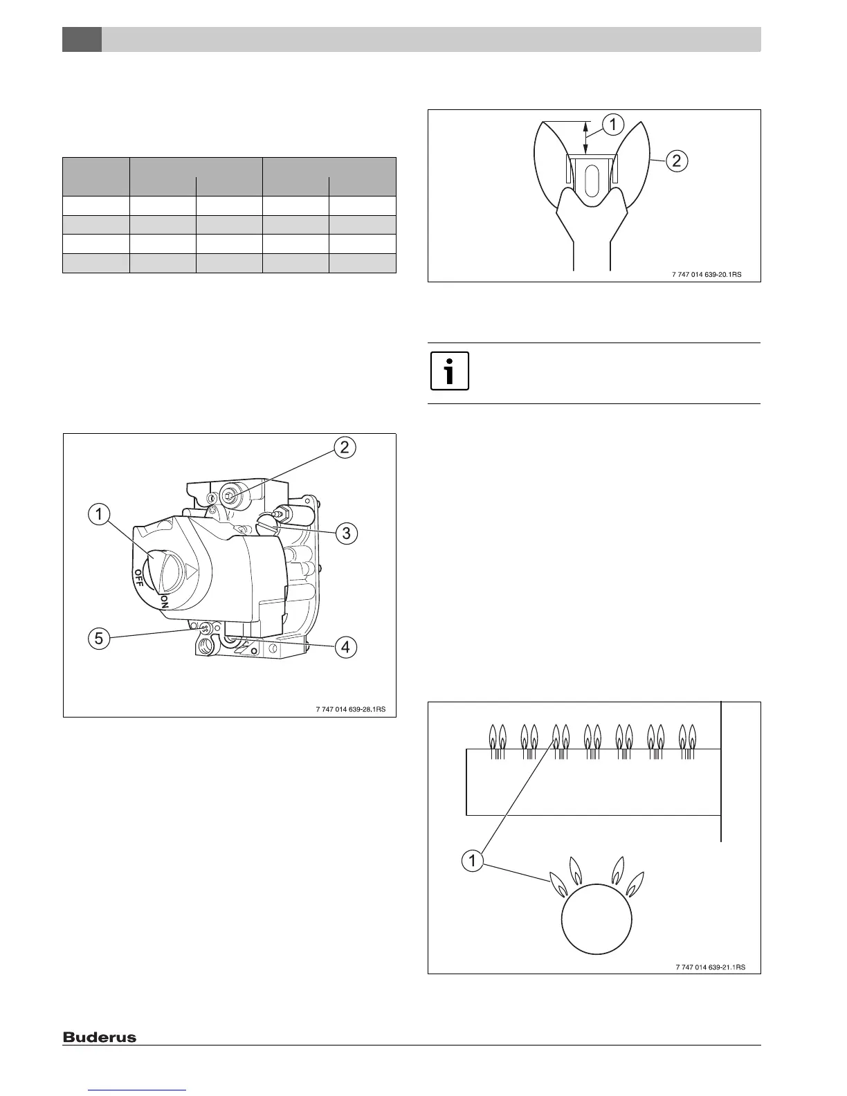
13. Observe pilot flame through the inspection hole in the burner cover
( Fig. 21, page 19).
14. The flame must surround the flame rod by 1/2 to
1 1/2 inches (15 to 40 mm). If this is the case continue with step 20.
Fig. 24 Correct pilot flame setting
[1] 1/2 to 1 1/2 Inch (12.7 to 38.1 mm)
[2] Pilot flame
15. If the ignition flame is too small or too large, the nozzle pressure for
pilot burner must be adjusted with the corresponding adjustment
screw.
16. Remove the safety screw for ignition nozzle pressure setting
(Fig. 23, [5]). Turn the inner adjustment screw clockwise to reduce
the pilot flame and counterclockwise to enlarge the pilot flame.
17. After adjustment tighten the pilot burner pressure adjustment safety
screw (Fig. 23, [5]) again.
18. Observe pilot flame [1] through the inspection hole in the burner
cover ( Fig. 21, page 19). The flame must have a steady and fixed
contour and generally has a bluish color.
If the main burner flame meets the requirements, proceed with step
21.
If the main burner flame is too weak or is yellow or goes out, turn the
ON/OFF switch on the gas shut-off valve (Fig. 23, [1]) clockwise to
OFF. Close the gas shut-off valve and disconnect the heating system
from the power supply and contact the customer service technician or
the gas supply utility.
Fig. 25 Main burner
[1] Main burner flame
Boiler
capacity
Natural Gas Propane
[Inch W.C.] [mbar] [Inch W.C.] [mbar]
38 3.0 7.6 10.6 26.5
45 4.1 10.4 10.5 26.2
55 4.6 11.5 10.3 25.8
64 4.4 10.9 10.3 25.9
Table 11 Nozzle pressure
The adjustment screw for the pilot ignition pressure
setting is behind the pilot burner adjustment safety
screw (Fig. 23, [5]).

 Loading...