9
Electrical circuit diagrams
Logano G234X – 6 720 804 886 (2012/08)30
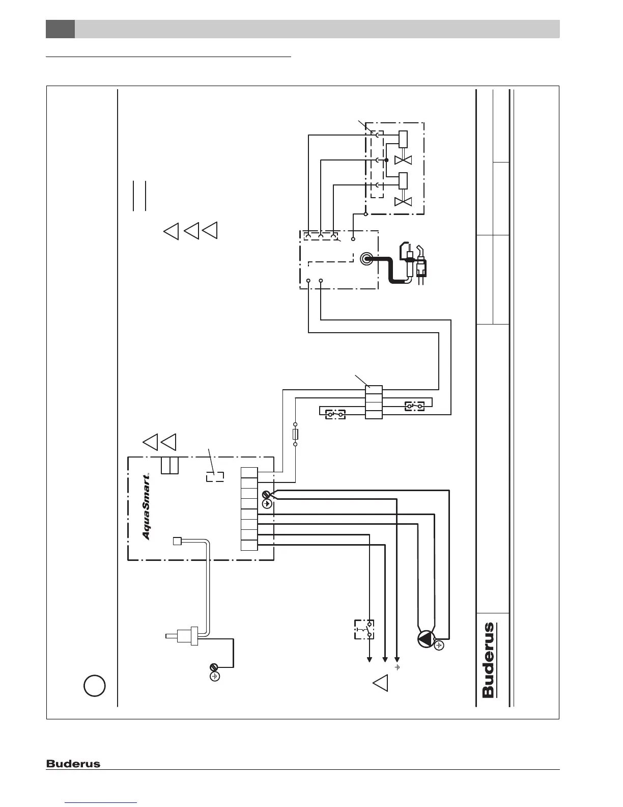
9 Electrical circuit diagrams
Fig. 41 Wiring Diagram - G234X
US
Wiring diagram gas-boiler G234X USA-CDN
Intermittent pilot
8469
8718588667
Plug
Plug
orange
black
PV
white
black white
black
Intermittent pilot control module S8600H
2012/11
GAW 034 USA
Burner assembly
Terminals on boiler block
Flame roll out
safety
shutoff means
Blocked vent
switch
Intermittent pilot dual
valve combination gas
control VR8304
Pilot burner
(Honeywell)
Main valvePilot valve
green
blue
white
red
GND
MV
MV
PV
GND
PV
MV/PV
MV
24V
24V
43
21
Ref. no. :
Drwg. no.:
Reviewed :
Edition :
Wiring diagram :
Optional Vent
Damper Plug
R
W
L2
Circulator
N
L
1
Emergency
Shut-off Switch
(by others)
L1 C1
C2 ZC ZR B1 B2
2
Boiler Sensor
Plug
3
Fuse
1,25AT
24V AWG 18 WIRE
120 VAC
Connecting terminals for thermostat
2
Main supply power - use circuit breaker
as required by code
1
Connecting terminals for outdoor sensor (optional)
3
orange
black
yellow
6 720 804 886-06.2T

 Loading...