TRI-FLEX II BED - OPERATION MANUAL 9
Operational Instruction
I.V Poles
If needed, I.V. support poles can be attached to each corner of the bed base frame.
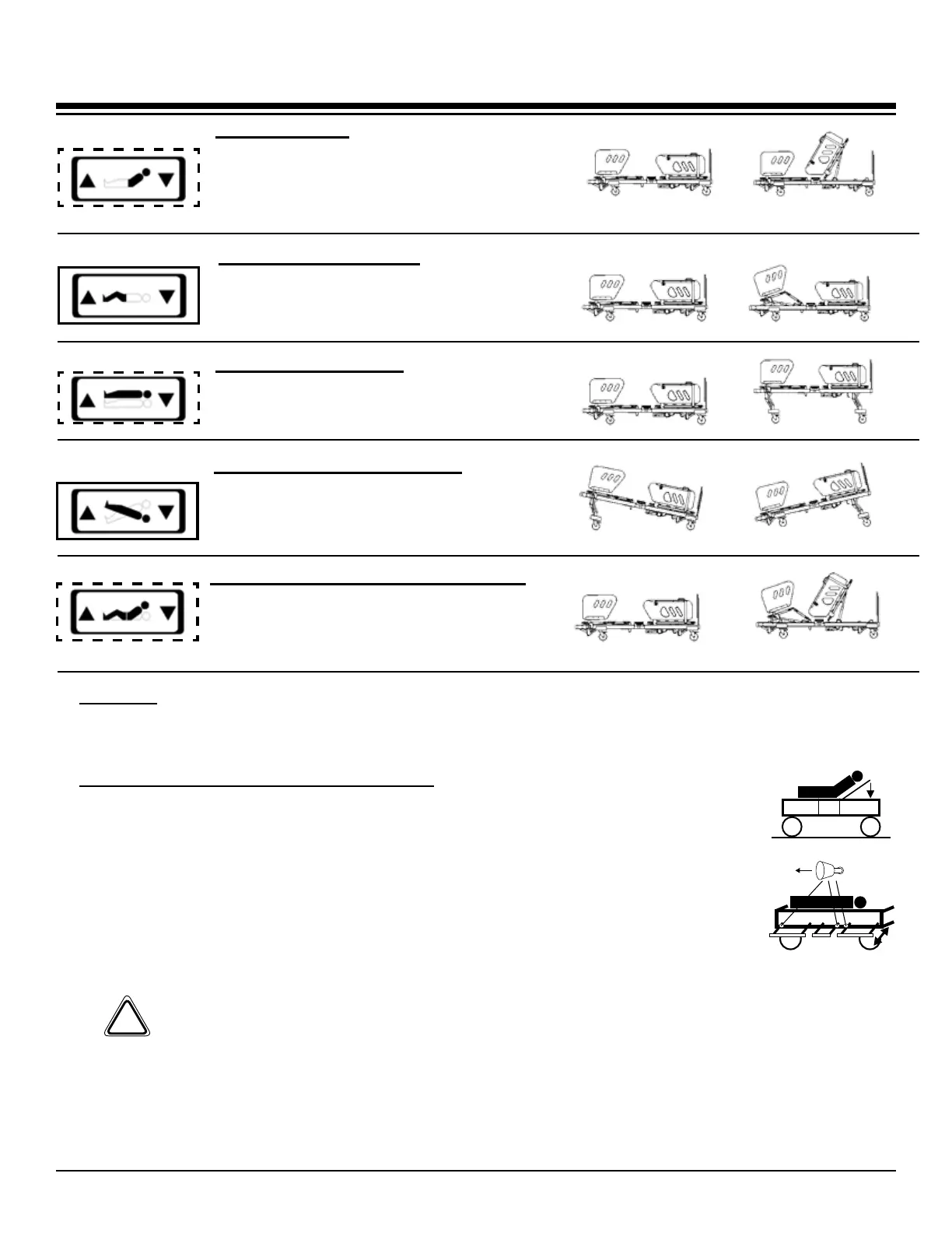
Head Elevation
Press and hold the top Up or Down
button on the hand pendant to raise or
lower the head of the bed as desired.
Maximum head elevation is 60 degrees .
Head & Foot / Knee (Up-Down)
Press and hold the bottom Up or
Down button on the hand pendant to
Raise/Lower the Head and Foot/Knee
at the same time.
Trendelenberg Function
To access the Trendelenberg position
press and hold the fourth Up or Down
button on the hand pendant to tilt or
reverse the bed as needed.
Bed Elevation (Hi-Lo)
Press and hold the third Up or Down
button on the hand pendant to raise or
lower the bed as desired.
Foot / Knee (Up-Down)
Press and hold the second Up or Down
button on the hand pendant to raise or
lower the foot as desired.
WARNING: Be sure to fully reengage the lock pin when adjusting the width of the bed.
TomaximizethefullscopeofUL60601-1/IEC60601-2-38(1996;1999),thisbedisintendedforpatient
useinONLYTHE122cm(48”)OR137cm(54”)WIDTHCONFIGURATIONS.
Within the current standard, patient and caregivers are safely removed from pinch points and moving
componentswhichcouldcauseharm.Congurationsotherthandescribedreducethedistancetothese
points which could result in severe personal injury or equipment damage.
Side Rail Width and Height Adjustments
To attach the side rails to the bed, you must insert the side rail support frame into
the horizontal tubes under the patient surface. Retract the stop pin by hand until
youcanpasstheframeatleast5cm(2”)intothebedgatch.Releasethestoppin
and continue to insert the support frame to the desired width. To adjust the width,
retract the stop pin and slide the support frame to the in or out position.
To remove the side rail support frame, slowly pull the frame out until it fully engages
the stop pin. Manually retract the stop pin and continue to remove the arm. Nor-
mally, the siderail support frame should not be completely removed for anything
other than setup or maintenance.
Stop Pin Location
!
 Loading...
