10 TRI-FLEX II BED - OPERATION MANUAL
Operational Instructions
BURKE INC. TRI-FLEX II
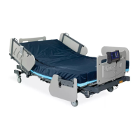
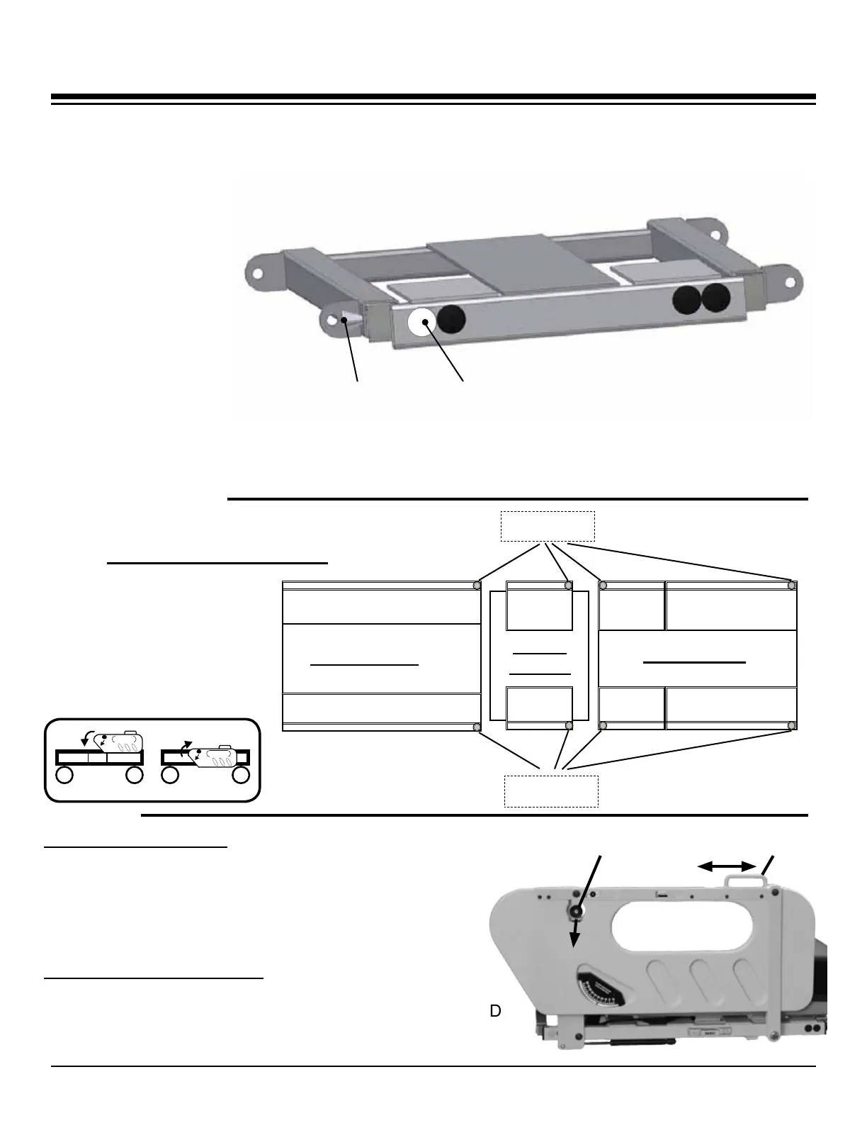
LOCATING PULLOUT RELEASE PINS (Pull Pins)
The Tri-Flex II has
a white/gray plug at
one end of each pull-
out (with exception of
Center Pullouts). The
location of the plug cor-
responds with the loca-
tion of the pull pin that
releases the pullout.
With this feature the
pull pins can be located
more easily when the
pullouts are extended
to their widest position.
The Diagram below
also indicates the loca-
tions of the pull pins.
HEAD SIDE RAIL LOCK - To release lock, Grasp around knob/
lock edges and pull outward while lifting hand loop. Knob will
autolock only when side rail is returned to the full upright posi-
tion. Side rail only locks in full upright postion.
Ensure lock is fully engaged after side rail returns to full
upright postition.
TO MOVE HEAD SIDE RAIL - movement of side rail
should only be performed using hand loop as shown.
Release lock, grasp hand loop and move side rail TOWARD
FOOT END of bed. Side rail only locks in full up position.
Foot Section
Center
Section
Head Section
Foot Pullout (L)
Foot Pullout (R) Knee
Pullout
Knee
Pullout
Center
Pullout
Center
Pullout
Head Pullout (L)
Head Pullout (R)
Top View
of Bed
Pull Pins
(Left side of bed)
Pull Pins
(Right side of bed)
Hand LoopHead Side Rail Lock
Pull Outward
To Unlock
Pull Pin Locations
PULL PIN WHITE/GRAY PLUG
Figure 1
Figure 2
Figure 3
 Loading...
