18 TRI-FLEX II BED - OPERATION MANUAL
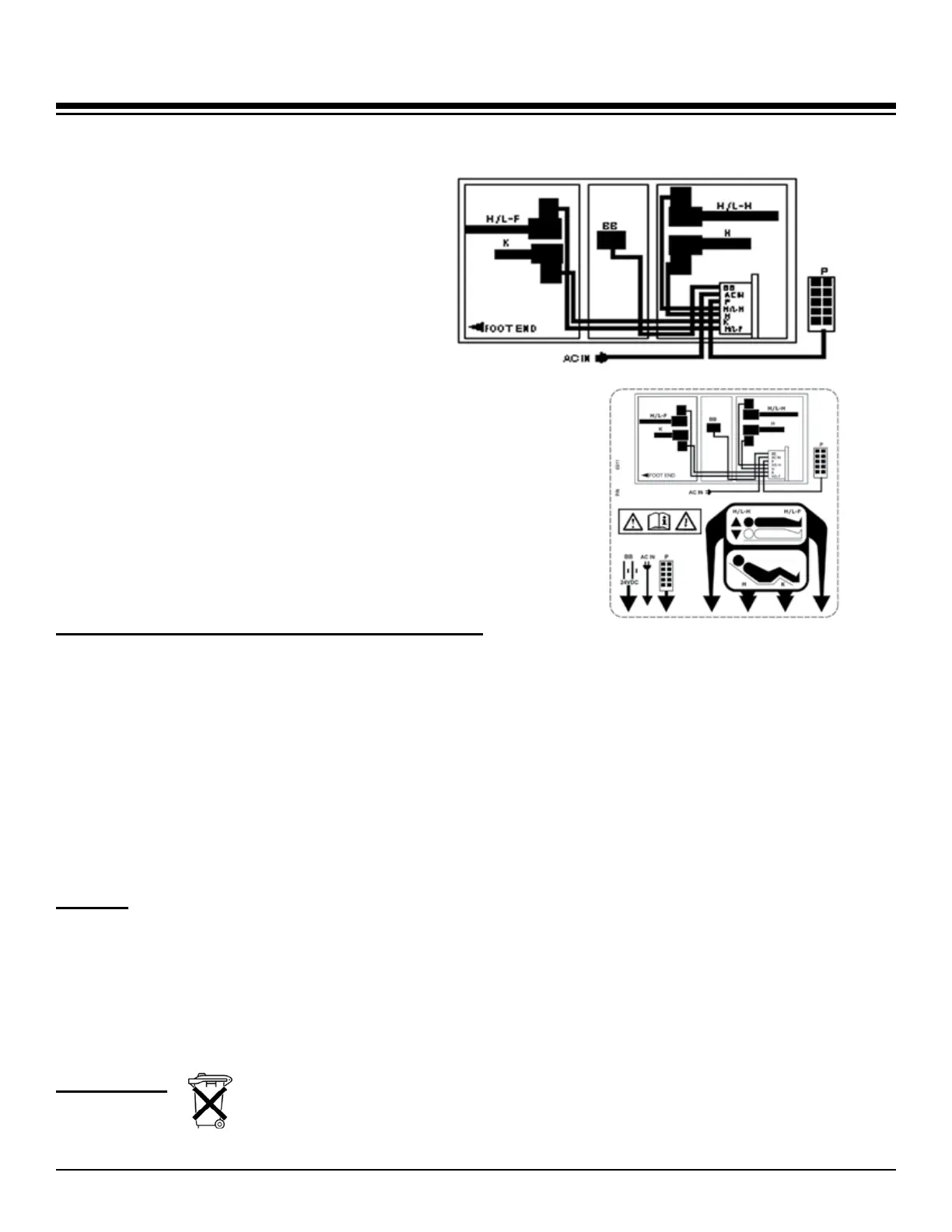
H =Headgatchactuator
K =Kneegatchactuator
H/L-H=Hi/LoHeadactuator
H/L-F=Hi/LoFootactuator
BB =BatteryBackup
P =Pendant
ACIN=ACpowercord
Control Box
Control Schematics
Control Box Label
The control box for the bed is located
under the head gatch on the left side
of the bed. This schematic is also on
a label located on the control box.
The abbreviations are as follows:
BATTERY AND CHARGER INFORMATION
Battery is in a sealed container, cannot be accessed.
Battery automatically charges when the bed is plugged in.
Auniquecircleconnectionismarkedtopreventincorrectttings.
All connect, disconnect and reconnect motions are a push-in pull-out connection.
Clean outside of battery box during regular maintenance.
The battery typically requires 8 hours to charge, depending on conditions, use or storage.
This battery and charger are part of a CE approved system that meets the IEC 60601.
It is not life sustaining or life supporting.
FUSES
The control box located under the left side of the head gatch has two line fuses located
behind a round removable plug located on the underside of the box. A pair of pliers can
grasp the “handle” of the plug and extract it from the box.
The fuses are designated as follows:
5x20mm 1.6L250V Time-Lag fuse (1.6A/250V) Wickmann Series 19195 or equivalent
DISPOSAL
The bed and various components consist of plastic,
metal parts and electrical components.
Recycle per local, state or national regulations.


 To Next Page