17
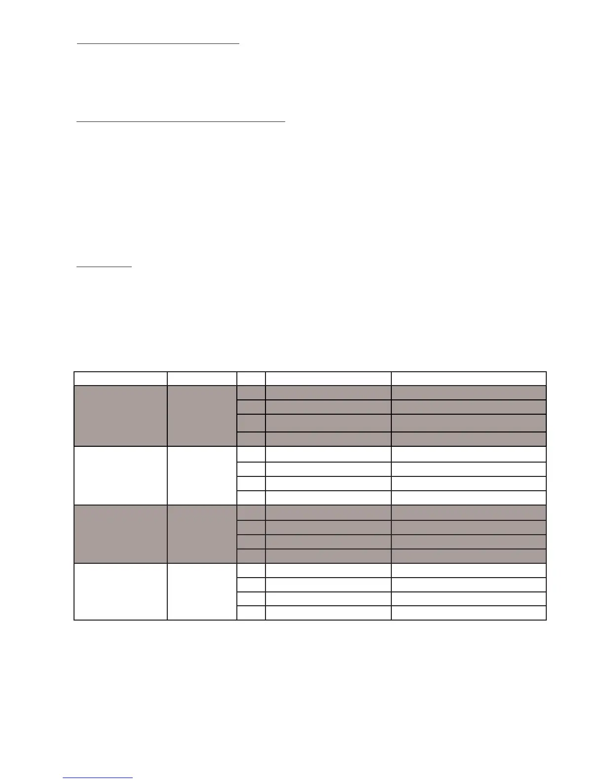
TABLE 7.5: PERMISSIBLE STAINLESS STEEL VENT SYSTEMS AND
PRINCIPLE VENT COMPONENTS (VENT OPTIONS 2, 5)
MANUFACTURER VENTSYSTEM SIZE COMPONENT PARTNUMBER
HEATFAB
SAF-TVENT
EZSEAL
3 BOILER
COLLAR 101004-01
3 WALLTHIMBLE HEATFAB7393,7393GCS,5391CI
3 HORIZONTALTERMINAL 8110701
3 VERTICALTERMINAL HEATFAB9392
PROTECH
SYSTEMS
INC.
FASNSEAL
3 BOILER
COLLAR 101004-01
3 W
ALLTHIMBLE FSWT3
3 HORIZONTALTERMINAL 8110701
3 VERTICALTERMINAL FSBS3
Z-FLEX
SVE
SERIES
III
(“Z-VENTIII”)
3 BOILER
COLLAR 101004-01
3 W
ALLTHIMBLE 2SVSWTEF03
3 HORIZONT
ALTERMINAL 8110701
3 VERTICALTERMINAL 24SVSTPF03
METAL-FAB CORR/GUARD
3 BOILERCOLLAR 101004-01
3 WALLTHIMBLE CGSWWPK(3")
3 HORIZONTALTERMINAL 8110701
3 VERTICALTERMINAL CGSWHTM(3")
NOTES:
1) Seeventsystemmanufacturer’sliteratureforotherpartnumbersthatarerequiredsuchasstraight
pipe,elbows,restopsandventsupports.
2) PartNo.101004-01collarreplacesfactory-mountedconcentriccollar(Figure7.16).
6)PermittedTerminalsforVerticalVenting -
• Vent Option 5-Astraightterminationisinstalledintheendoftheventpipe.Ventmanufacturerpartnumbersforthese
screensareshowninTable7.5.Theairinletterminalconsistsofa180degreeelbow(ortwo90degreeelbows)witha
rodentscreenasshowninFigure7.10
• Vent Option 6-UseU.S.Boilerpart101495-01withtheappropriateashing(seeTable7.4b).
7)VerticalVentTerminalLocations(VentOptions5,6)-Observethefollowinglimitationsonthelocationofallverticalvent
terminals(seeFigures7.10and7.11):
• Thetopoftheventpipemustbeatleast2feetaboveanyobjectlocatedwithin10feet.
• ForVentOption#5,theverticaldistancebetweentopoftheventandairinletterminalopeningsmustbeatleast12".
• Thebottomoftheairinletterminalmustbeatleast12”abovethenormalsnowaccumulationthatcanbeexpectedon
theroof.TheterminalusedinVentOption#6hasaxeddistanceabovethestormcollarof19".Ifagreaterdistance
isneededtoprovidetheclearanceabovethesnowline,buildachaseontheroofandmounttheverticalterminalontop
ofthechase.
• ForVentOption#5,theairintaketerminalmustbelocatedontheroofandmustbenofurtherthan24"horizontally
fromtheexhaustpipe.
8) Wallthimbles–Wallthimblesarerequiredwheresinglewallventpipepassesthroughcombustiblewallswithlessthan
therequiredclearanceshowninTable4.2orasrequiredbylocalcodes.Stainlessventmanufacturer’swallthimblepart
numbersareshowninTable7.5.Notethatconcentricventhasa"zero"clearancetocombustiblesandthereforedoesnot
requiretheuseofwallthimbles.