33
d) Completetheventsysteminsidethestructure.ThesupportelbowsitsontheM10x35screwasshowninFigure
7.34.CuttheWallPenetrationSectiontothelengthrequiredtoconnecttheinteriorventsystemtotheSupportElbow
followingtheinstructionsonPage27.
e)RemovetheSupportElbowfromtheLowerSupportBracketandattachittotheWallPenetrationSection.Slipthis
assemblythroughtheLowerSupportBracket.Connecttotheinteriorventsystem.
f) SlideanOuterJointGasketoverthemaleendoftheAirIntakeSectionwiththetaperededgeofthegasketpointing
up.AttachtheAirIntakeSectiontotheSupportElbow.Ifnecessary,theAirIntakeSectioncanbeshortenedby
cuttingthemaleendasdescribedonpage27.AfterattachingtheAirIntakeSectiontotheSupportElbow,slidethe
OuterJointGasketdownoverthejointbetweenthetwottingstopreventraininltration.
g) AttachtheWallbrackettothewall0”-6”fromthebottomedgeoftheintakebell(Figure7.34).Use1/4”screws(not
provided)tomountthisbracket.
h)SlidetheremainingOuterJointGasketoverthemaleendoftheTerminalElbow.AttachtheTerminalElbowtothe
AirIntakeSection,pointingitawayfromthewall.SecuretheTerminalElbowtotheAirIntakesectionwithasingle
#10x1/2”sheetmetalscrew(Figure7.34).Drilla1/8holethroughbothouterpipestostartthisscrew.Use a drill
stop or other means to ensure that the drill bit does not penetrate more than 3/8” into the outer pipe. Do not
use a sheet metal screw longer than 1/2”.SlidetheOuterJointGasketdownoverthejointbetweentheTerminal
ElbowandtheAirIntakeSectiontopreventraininltration.
i) AttachtheExhaustTerminaltotheTerminalElbow(Figure7.34).
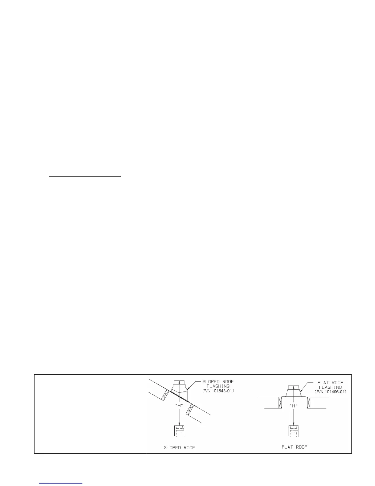
6) VerticalTerminalInstallation-Inadditiontotheverticalterminal,eitheraFlatRoofFlashing(P/N101496-01)orSloped
RoofFlashing(P/N101543-01)isrequiredforthisinstallation.
a) Determinethecenterlineoftheterminallocationontheroof.Iftheroofisat,cuta5-1/2”diameterholeforthe
terminal.Iftheroofissloped,cutaholelargeenoughfortheterminaltopassthroughtheroofwhileremaining
plumb.Caution: If the boiler is installed directly under the hole, cover it while cutting the hole to prevent saw
dust and other debris from falling into the boiler.
b)Installtheroofashingusingstandardpracticefortheroongsystemonthestructure.
c)Ifnotalreadydone,assembletheventingsysteminsidethebuilding.Thelastsectionofpipeneedstobeonthesame
centerlineastheterminalandwithin19-1/4”ofthetopedgeoftheroofashing(Figure7.35a).
d)Measuredistance“H”fromthetopedgeofthestormcollartotheendofthelastttingasshowninFigure7.35a.
e)Add1”todistance“H”.CarefullymarkthislengthonthepipeasshowninFigure7.35b.
f) Cuttheouter pipe onlyatthepointmarkedinStep(e)usingaviationshears,ahacksaw,oranabrasivewheelcutter.
Becarefultocutthepipesquare.De-burrthecutendwithaleoremerycloth.
g)Placeamarkonthealuminuminnerpipe3/8”beyondtheendoftheouterpipe(Figure7.35b).Useanetooth
hacksawtocutthealuminumpipeandbecarefultocutthepipesquare.De-burrthecutedgeofthealuminumpipe
withaleoremerycloth.
h)Makeamarkontheterminalsection1”fromthecutendoftheouterpipeasshowninFigure7.35b.
i) Sliptheterminalsectionthroughtherooffromtheoutside.Pushintothelastsectionofventpipeuntilthemark
madeinStep(h)isnotlongervisible.Securetheterminaltothelastpieceofpipewiththree#10x1/2”sheetmetal
screws.Drilla1/8”holethroughbothouterpipestostartthesescrews.Use a drill stop or other means to ensure
that the drill bit does not penetrate more than 3/8” into the outer pipe. Do not use a sheet metal screw longer
than 1/2”.
j) Securetheterminalsectiontotheinsideoftheroofstructureusingthemountingbracketprovidedwiththeterminal
(Figure7.35c).
Figure 7.35a: Dimension "H"