83
107774-01- 9/17
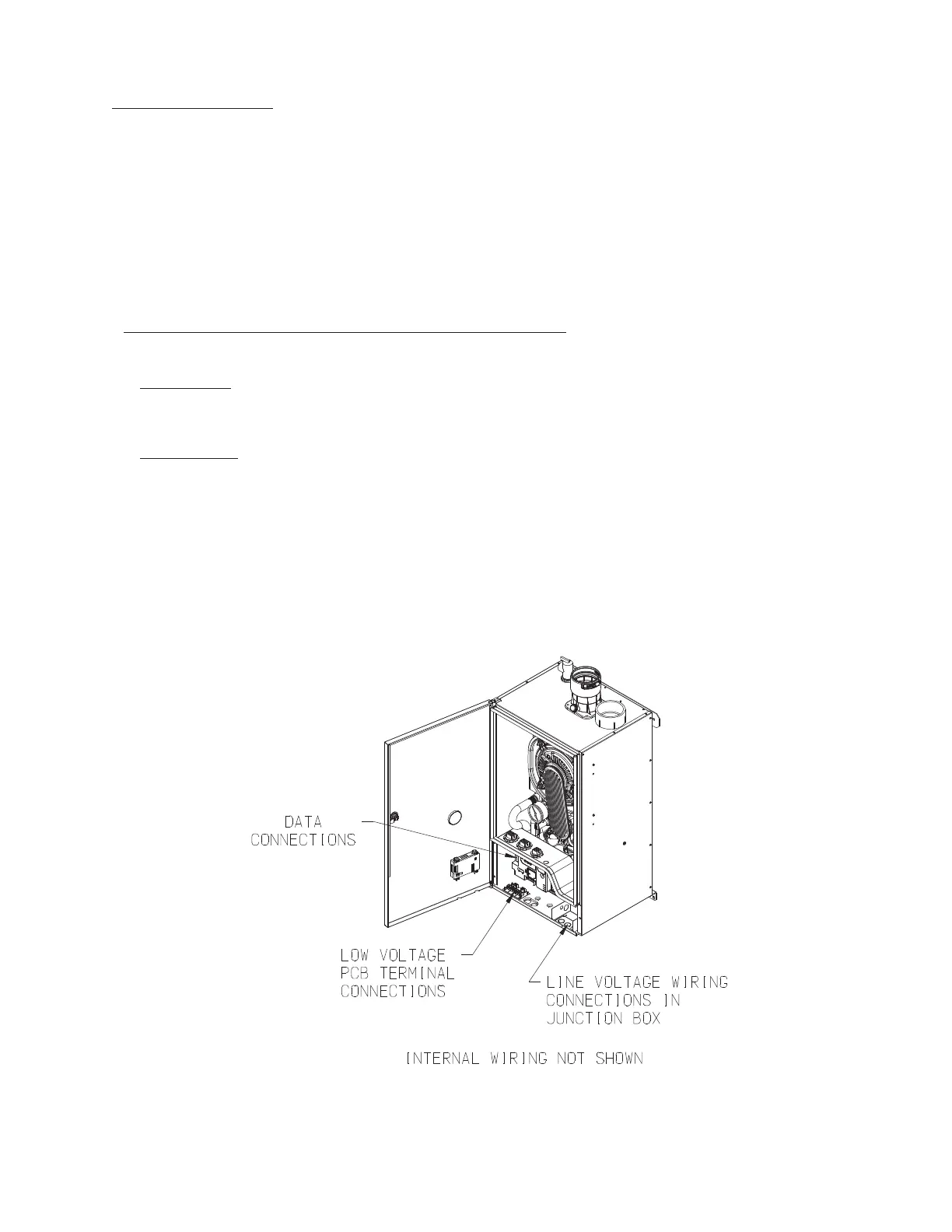
Figure 11.1: Location of High and Low Voltage Field Electrical Connections
XI. Wiring (continued)
2) Low Voltage Connections–CommonlyusedlowvoltageeldconnectionsarelocatedonthelowvoltagePCBandareshown
in Figure 11.3 and listed from left to right:
1 Heat T’Stat - 24VAC heating thermostat
2 Heat T’Stat - 24VAC heating thermostat
3 DHWStat-Noeldconnection
4 DHWStat-Noeldconnection
5 External Limit - Field supplied low voltage safety limit contacts (1)
6 External Limit - Field supplied low voltage safety limit contacts (2)
7 Outdoor Sensor - Tasseron TSA00AA Outdoor Temperature Sensor (1)
8 Outdoor Sensor - Tasseron TSA00AA Outdoor Temperature Sensor (2)
External power must not be applied to any of the low voltage terminals - doing so may damage the boiler control. Also note
the following:
a) External Limit-Theexternallimitterminalsareintendedforusewithaeldsuppliedsafetydevice,suchasamanual
reset high limit or low-water cut-off. When an external limit is used, the jumper between these two terminals must be
removed. Failure to remove this jumper will render the external safety devices ineffective.
b) Outdoor Sensor - Use only the Tasseron TSA00AA outdoor sensor supplied with the boiler. When this sensor is con-
nected and enabled, the boiler will adjust the target supply water temperature downwards as the outdoor air temperature
increases. This sensor should be located on the outside of the structure in an area where it will sense the average air
temperature around the house. Avoid placing this sensor in areas where it may be covered with ice or snow. In general,
locations where the sensor will pick up direct radiation from the sun should also be avoided. Avoid placing the sensor
nearpotentialsourcesofelectricalnoisesuchastransformers,powerlines,anduorescentlighting.Wirethesensorto
the boiler using 22 gauge or larger wire. As with the sensor itself, the sensor wiring should be routed away from sources
of electrical noise. Where it is impossible to avoid such noise sources, wire the sensor using a 2 conductor, UL Type
CM, AWM Style 2092 shielded cable. Connect one end of the shielding on this cable to ground. See Section XIII of this
manual for information on enabling the outdoor reset sensor.