Fiskars Boats, Inha Works Ltd 2010
13 (31)
5.8 Electrical system
The circuit diagram for the electrical systems of the boat is shown in Appendix 3.
The main power switch and fuse box are located in the storage space of the rear seat
on the left-hand side of the boat. The circuitry of the boat functions when the switch
key is turned clockwise into a horizontal position. When the key is in a vertical
position, the circuitry is off. The automatic bilge pump is always functional
irrespective of the position of the main power switch. The battery is located in the
equipment space under the left side of the rear seat. The capacity of the battery is
high, but prolonged use of the boat's electrical equipment should be avoided to avoid
start-up problems.
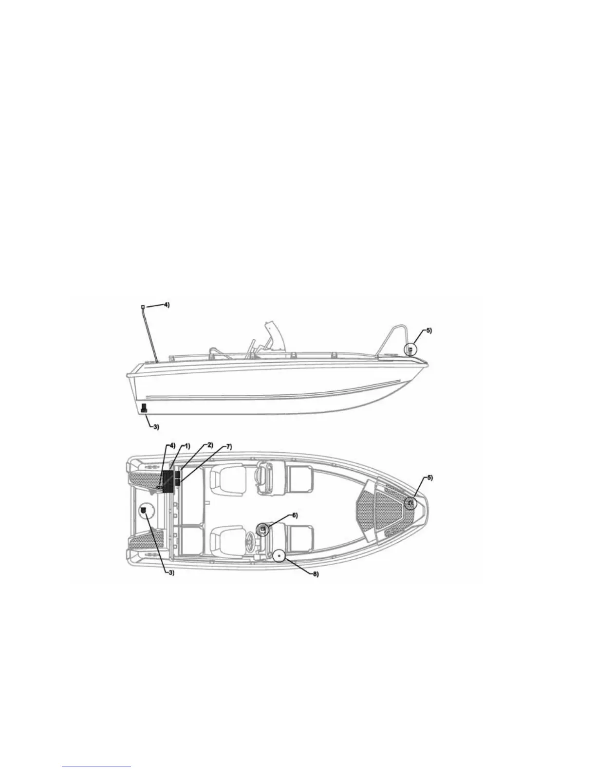
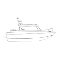
The electrical devices and their switches are located as shown in Diagram 4.
Diagram 4. Location of electrical devices:
1) Accumulator housing;
2) Main power switch;
3) Bilge pump;
4) Mast light, white 360
q
;
5) Navigation lights, with colour sectors;
6) Switch panel (see Diagram 5.);
7) Fuse box (see Diagram 6.);
8) Power socket 12 V, 10A