INSTRUCTION, USE AND
MAINTENANCE MANUAL
GB
Page 40 of 67
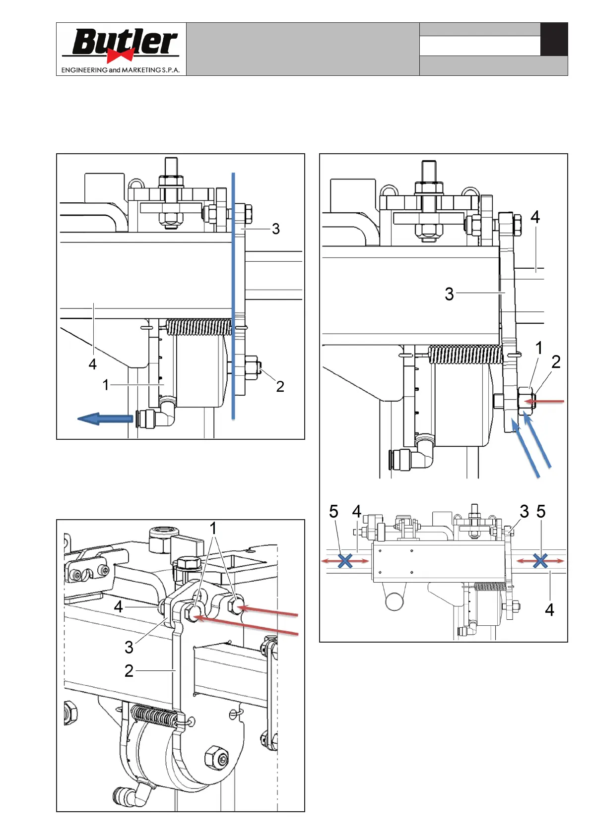
a. Blow off the compressed air from neck’s cylinder
(Fig. 55 ref. 1). Make neck (Fig. 55 ref. 3) reach
beat position again on the guide support surface
(Fig. 55 ref. 4), by turning the adjusting dowel (Fig.
55 ref. 2).
Fig. 55
b. Completely screw fulcrum-type screw (or screws)
(Fig. 56 ref. 1) but without locking them, just mak-
ing them approach, setting a 0.1 ÷ 0.2 mm play
between neck (Fig. 56 ref. 2) and adjusting plate
(Fig. 56 ref. 3), positioning nut (Fig. 56 ref. 4) and
letting it rest completely onto adjusting plate.
Fig. 56
c. Slacken lock nut (Fig. 57 ref. 1) of adjusting
dowel (Fig. 57 ref. 2). Then, slacken dowel (Fig.
57 ref. 2) until neck (Fig. 57 ref. 3) strikes onto
arm (Fig. 57 ref. 4), that as a consequence results
clamped (Fig. 57 ref. 5).
Fig. 57
CAPTURE 4 - CAPTURE 4 FI
7104-M007-4_B