INSTRUCTION, USE AND
MAINTENANCE MANUAL
GB
Page 41 of 67
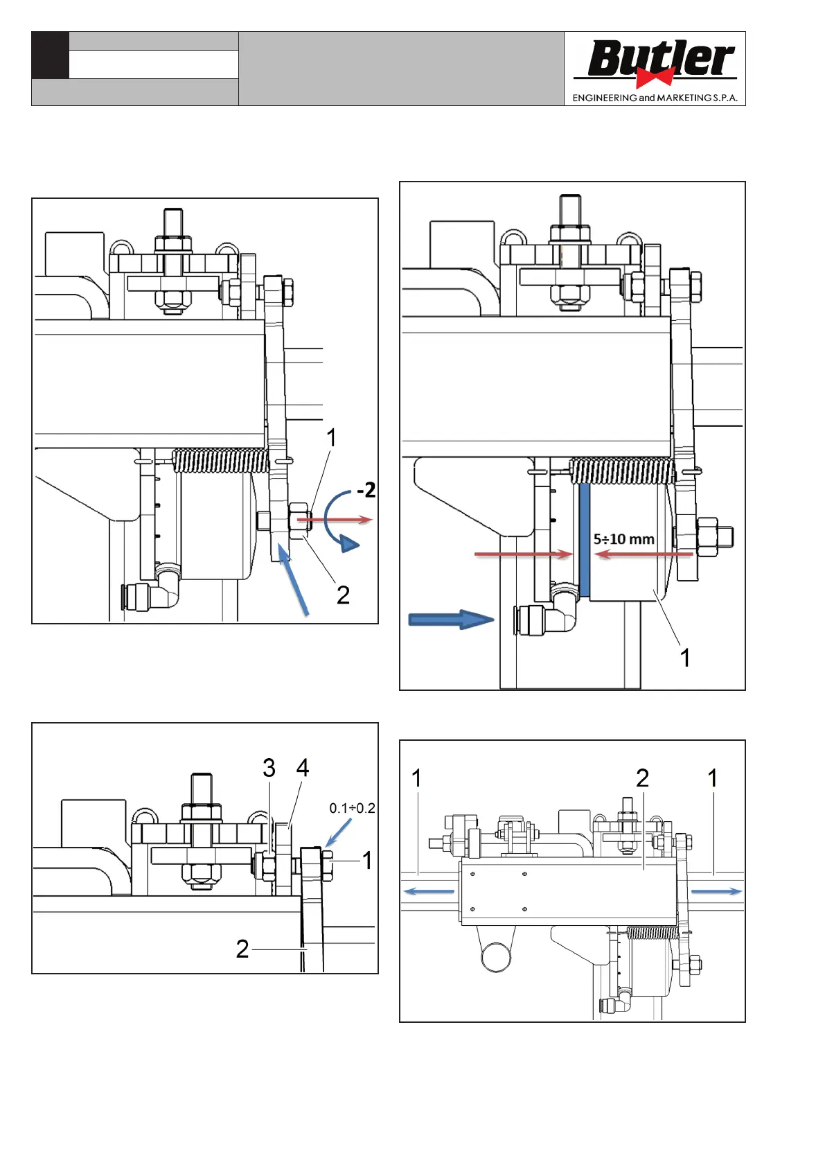
d. Starting from the position reached at point (c),
screw neck’s adjusting dowel counter-clockwise
of 2 complete turns (Fig. 58 ref. 1) and lock the
relevant counter nut (Fig. 58 ref. 2).
Fig. 58
e. Turn fulcrum-type screw (or screws) (Fig. 59 ref. 1)
in order to reset 0.1 ÷ 0.2 mm play between neck
(Fig. 59 ref. 2) and fulcrum-type screws’ head
(Fig. 59 ref. 1), letting nut (Fig. 59 ref. 3) rest
completely onto adjusting plate (Fig. 59 ref. 4).
Fig. 59
f. Operate cylinder (Fig. 60 ref. 1), supplying it with
compressed air, and make sure its stroke is in-
cluded between 5 ÷ 10 mm.
Fig. 60
g. Blow off cylinder and make sure the arm (Fig. 61
ref. 1) can slide freely in its guide (Fig. 61 ref. 2).
Fig. 61
h. Repeat points (f) and (g) 3 times at least.
CAPTURE 4 - CAPTURE 4 FI
7104-M007-4_B