Installation
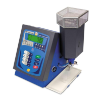
Embedded in the instrument enclosure is a built-in air
compressor. A unique electronic control system automatically
regulates the air pressure/flow to the optimum levels. No user
adjustments are necessary to achieve maximum performance.
Adjustments, if required, can be carried out in Service mode.
If an exterior alternate air source is desired, there is a hose
barb on the rear panel. The air source must be regulated to 10
PSI, offering 4L/min (measured in operational series) and be
free of oil, dust and airborne contaminates.
The air supply must not be oxygen enriched.
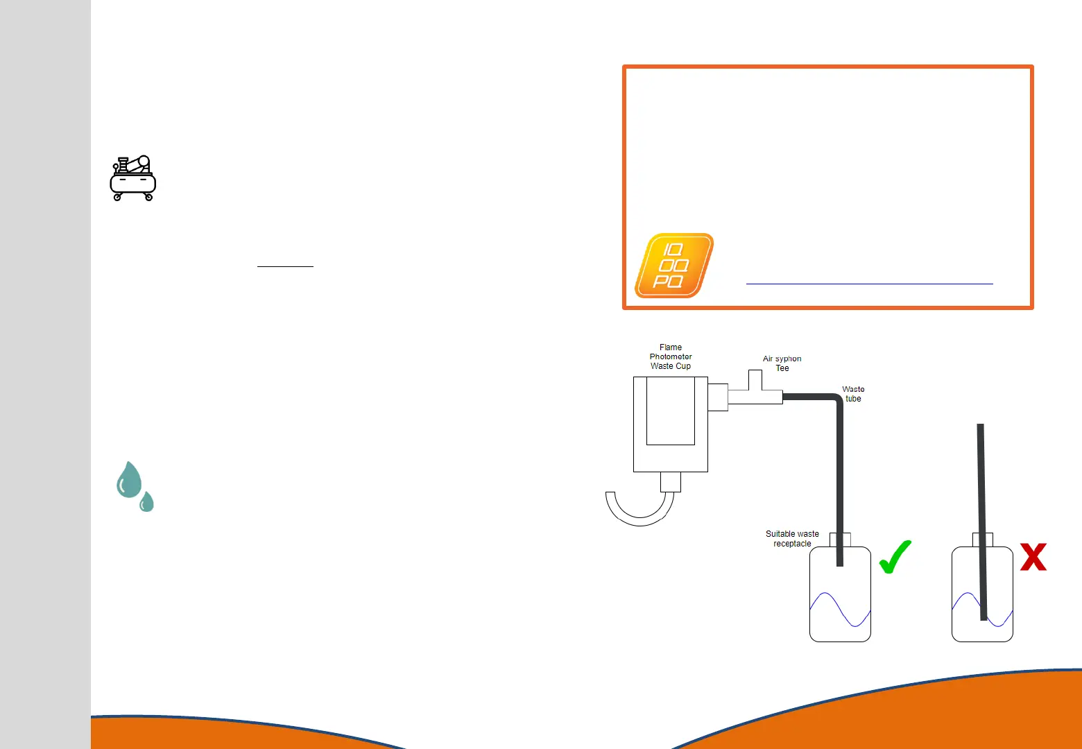
A sink or suitable container should be sited near the instrument
to dispose of the waste overflow from the Drain Cup. If a waste
container is used it should be situated so that the sides are
below the bottom of the Drain Cup. Attach the supplied silicone
tubing to the side port of the Drain Cup and route the other end
to the sink or waste container.
There should be a clear drain to waste without kinks or U-
sections and the end of the waste tube should be kept above
the water level in the waste bucket. The use of a T-piece just
after the drain cup is recommended to avoid the possibility of
forming a partial siphon.
NOTE: The end of the waste tube must never be submerged
below the waste liquid level as this may prevent the natural
draining of the beaker. This can cause erratic readings and
potentially flood the bench.
14
IQ OQ PQ
Our novel IQ OQ PQ programme enables a user to
successfully validate the installation of the new flame
photometer and operator functionality. Submission of the
report document to BWB results in certification for
performance and operation validation.
Find out more:
https://www.bwbtech.com/iq-oq-pq