A
VAC VOICE ALARM SYSTEM
A
VAC Installation and Maintenance Manual • Approved Document No. DAU000040 Rev 6 • Page 11
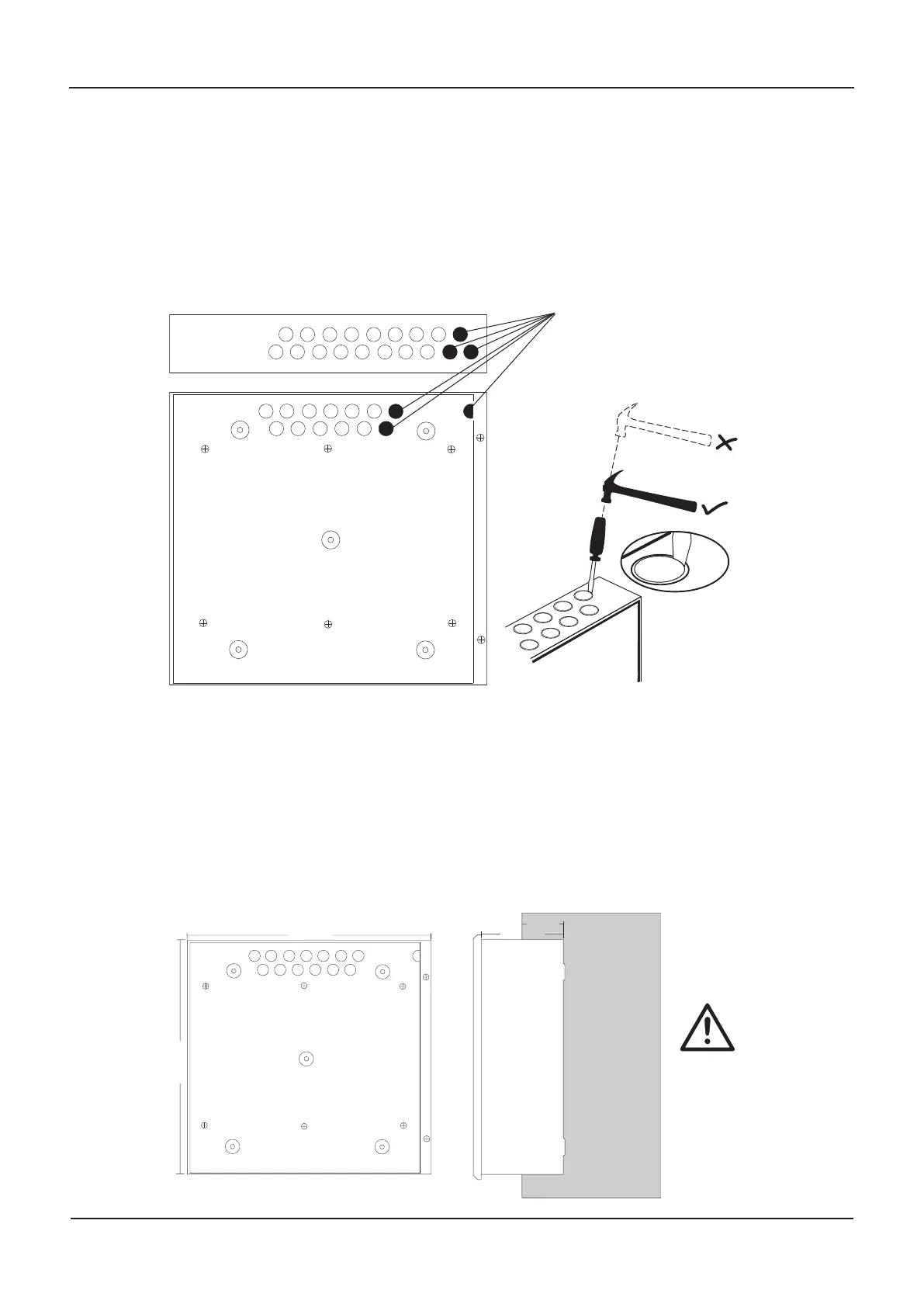
Planning the cable layout in the enclosure
All low voltage wiring coming into the enclosure should be segregated away from the 100 V
loudspeaker lines and incoming mains voltages. Refer to the diagram below for guidance and
important information on how to remove the enclosure’s knockouts. Always ensure that if a
knock-out is removed, the hole is filled with a good quality cable gland. Any unused knock-
outs must be securely blanked off.
Location of knockouts for cable entry and knockout removal details
Fixing the base to the wall
Using the five mounting holes provided (see diagram below), fix the base securely onto/into
the wall. The mounting holes ar
e suitable for use with No.8-10 or 4-5mm countersunk screws.
Assess the condition and construction of the wall and use a suitable screw fixing.
Any dust or swarf created during the fixing process must be kept out of the enclosure and
great care must be taken not to damage any wiring or components.
Internal view of the back box with PCBs removed / side view for flush mounting
Bring mains into the enclosure
t
hrough one of these knockouts
Knockouts should be
removed with a sharp tap in
the rim of the knockout using
a flat 6mm broad-bladed
screwdriver
420mm
420mm
WALL
115 mm
55 mm
CAUTION
If mounting multiple
A
V
AC masters (or slaves)
next to each other, take
car
e to leave a gap of at
least 80 mm between
each of their bases to
allow their lids to swing
www.acornfiresecurity.com
www.acornfiresecurity.com