A
VAC VOICE ALARM SYSTEM
AVAC Installation and Maintenance Manual • Approved Document No. DAU0000402 Rev 6 • Page 15
Loudspeaker Tapping
The most common installation problem on a voice alarm system is the incorrect tapping of
loudspeakers. If they are tapped at too high a wattage, the amplifier may be overloaded. If
they are tapped at too low a wattage, the sound may be too quiet.
Loudspeaker circuits
AVAC has two loudspeaker outputs, each of which can accommodate up to 60 watts of
loudspeaker load. For example 20 loudspeakers tapped at 3 watts or 40 loudspeakers tapped at
1.5 watts. We recommend however that you allow 20% spare capacity on each loudspeaker
circuit to accomodate future changes and/or tolerances within the circuit.
The continuous average output power of each circuit is 60 watts. Signals above this level will
be compressed and the ‘Audio Limit’ LED will illuminate to indicate that the sound source is
overdriving - see pages 19, 20 or 21 for further details.
To determine the actual loading (in watts) of a loudspeaker circuit with the speakers connected,
disconnect the loudspeaker circuit at the main PCB and measure the impedance of the cable
and loudspeakers using a Loadmaster or LCR meter. Remember that the maximim load for
each circuit is 60 watts, which is equivalent to a minimum impedance of 166 ohm
s.
To convert impedance into power, use the following equation:
P (power in watts) = 10,000 / Z (impedance in Ohms)
Example:- Z (impedance in ohms) = 334 ohms.
10,000 / 334 = 29.94. Therefore P = 30 watts.
An end of line module (EOL) provided in the accessory pack must be physically secured and
connected across the terminals of the last loudspeaker to allow the wiring to be monitored for
open or short circuit fault conditions. In order to check that the loudspeaker line monitoring is
operating correctly, fit the EOL in an accessible location.
We recommend C-TEC voice alarm loudspeakers are used as these have been tested for
correct operation with AVAC. All loudspeakers must be suitable for 100 volt line operation.
Low impedance loudspeakers will not work, will overload the amplifier and may be
seriously damaged. Note that a form is provided on page 30 where you can record the number,
type, location and tapping of each loudspeaker used.
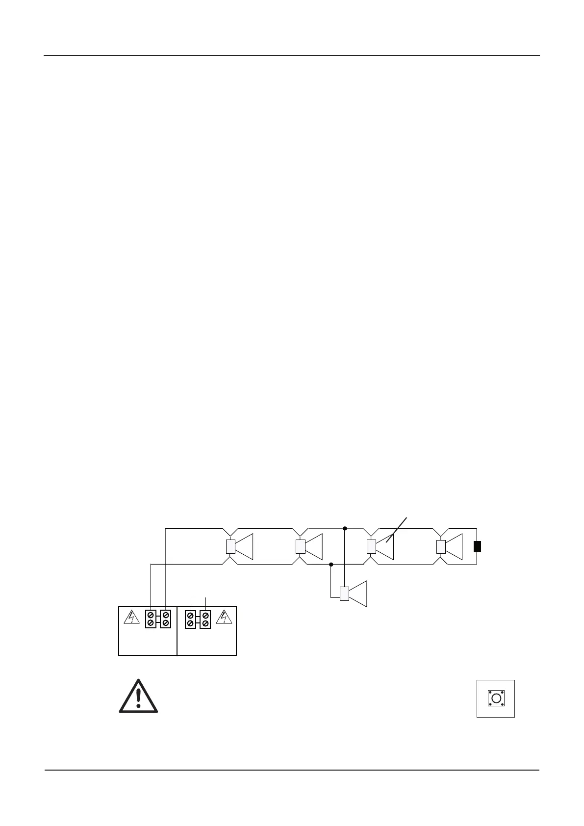
T
ypical loudspeaker cir
cuit wiring
LOUDSPEAKER CONNECTION
OV 100V
A
DO NOT SPUR
(WIRING NOT MONITORED)
END OF
LINE UNIT
It is common practice to ‘interleave’ the loudspeaker circuits to
maximise sound distribution in the event of one of the circuits failing.
Please refer to our seperate Guide to Voice Alarm Systems for details.
OV 100V
B
TO SPEAKER
CIRCUIT B
Calibrate
SW1
IMPOR
T
ANT
T
o ensur
e the loudspeaker cir
cuits are monitored cor
r
ectly
, they
MUST be calibrated using the SW1 button on the Indicator PCB
inside the lid. See page 16 for details.
Each speaker MUST have a line transformer suitable for
100 V operation tapped to the appr
opriate wattage
EOL
In open ar
eas, it is common practice to ‘interleave’ the loudspeaker
circuits to maximise sound distribution in the event of one of the
circuits failing.
www.acornfiresecurity.com
www.acornfiresecurity.com