A
VAC VOICE ALARM SYSTEM
A
VAC Installation and Maintenance Manual • Approved Document No. DAU0000402 Rev 6 • Page 20
PUBLIC ADDRESS PAGING CONNECTION
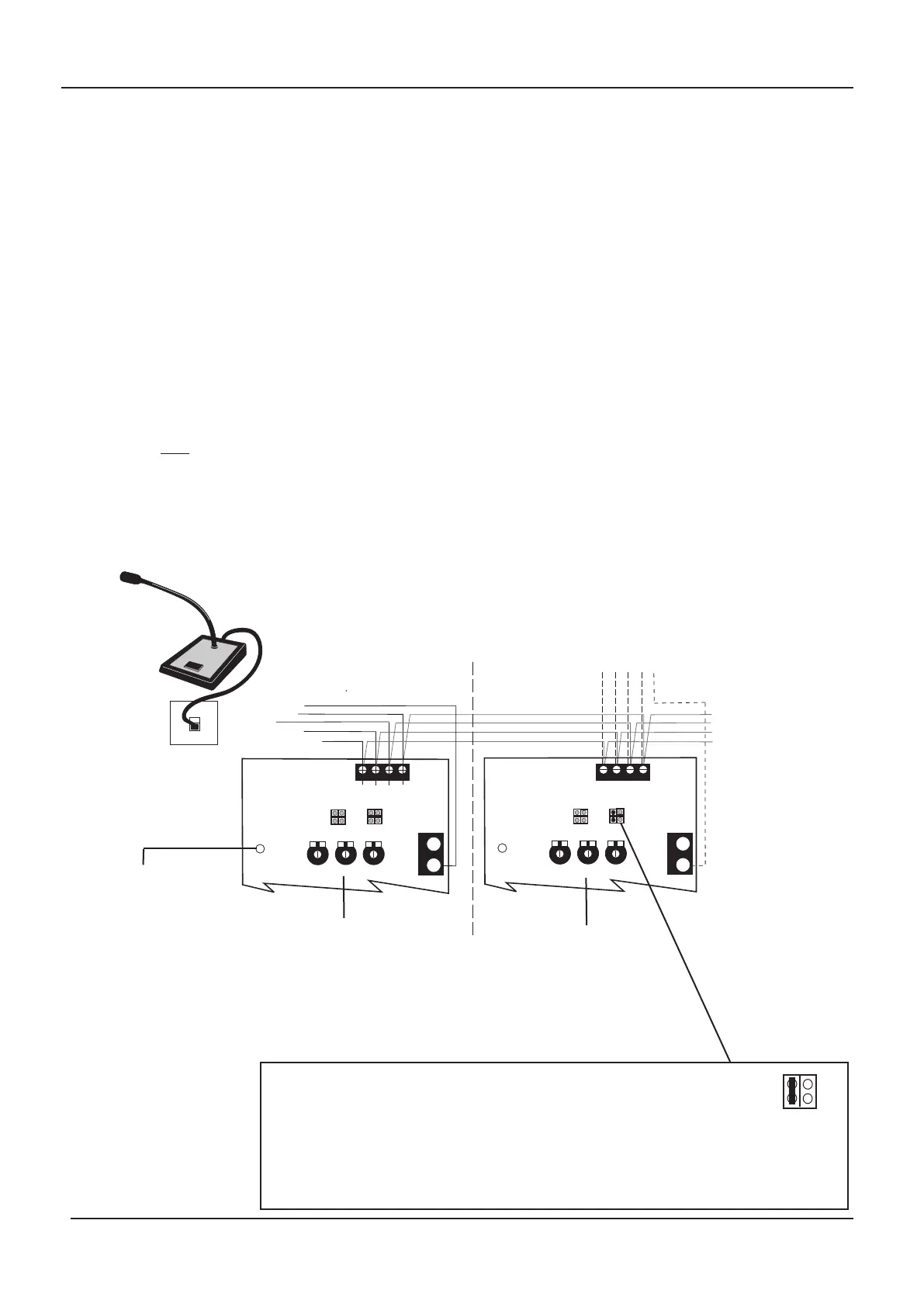
If required, a VA406 desk microphone console can be connected to the paging input for non-life
safety public address announcements. Note that other balanced line level equipment, such as the
output from a telephone system, may be connected instead. If in doubt, please contact your distribu-
tor for details.
The paging input is designed to accept balanced line level signals of between 300 mV and 1.5 V rms.
If you wish to connect a higher line level signal, fitting the right hand PLK3 link (
/10) on the Main
PCB will attenuate the input signal by a ratio of approximately 10:1.
The volume of the paging signal can be adjusted using the
Page level control on the Main PCB.
Please note, should the volume be set too high, the audio limit LED on the main PCB will illuminate
red to indicate that the audio signal is being clipped. If this happens, re-adjust the
Page level con-
trol until you are satisfied with the sound quality and the limit LED flickers red only very occasional-
ly. Failure to do so could lead to audio distortion.
For global paging, simply daisychain the paging input to all relevant AVAC master and slave units.
Note that if global paging is utilised, the left hand PLK3 link (
master/phantom) must be fitted at
the last
AVAC in the daisychain only. If local paging is used, then the left hand PLK3 link should be
fitted at every AVAC (master or slave) which has paging equipment connected directly to it).
Pressing the paging equipment’s PTT (push to talk) button will override all relevant background
music signals but have no ef
fect on higher priority triggers (such as Alert messages, Evacuate
messages or Emergency Mic broadcasts).
PTT
SIG 0V
MAIN
PCB 1
Paging Input
CAT 5 CABLE
CONTINUE DAISYCHAIN
TO NEXT AVAC FOR
OPTIONAL LARGER AREA
PAGING IF REQUIRED
PTT
SIG 0V
MAIN
PCB2
Paging Input
}
Local
F
ault
FireMic
PLK2
Master/
Phantom
P
age
PLK3
/
10
Audio
Limit
FireMic
Page
BGM
Local
Fault
F
ireMic
PLK2
Master/
Phantom
P
age
PLK3
/10
Audio
Limit
FireMic
Page
BGM
0V
+24V
A (+24V) white/orange
C (PTT) white/green
B (0V) orange
G (Audio-/Cold) brown
H (Audio+/Hot) white/brown
CATCON PLATE
(supplied with VA406
desk mic. console)
0V
+24V
Alternatively, connect an
additional VA406 here for
localised paging
Typical public address paging (VA406 desk microphone console) connection
Turn clockwise
to increase
paging volume
MASTER
AVAC UNIT
ADDITIONAL
MASTER
(OR SLAVE) AVAC UNIT
If global paging is utilised, the left hand PLK3 link (
Master/Phantom)
must ONLY be fitted at the last AVAC in the daisychain. In this example,
the link would
be fitted at Main PCB 2 only
.
• If only one master AVAC is used, the Master/Phantom PLK2 link would
be fitted on that AVAC’s Main PCB.
The audio limit
LED illuminates
red when the audio signal
is being clipped due to the
input or paging volume
being set too high. If this
occurs adjust the level(s)
accor
dingly until you ar
e
satisfied with the sound
and the limit LED flickers
red only very occasionally.
Turn clockwise
to increase
paging volume
Page
PLK3
Master/
Phantom
/10
• If localised paging is used, the Master/Phantom PLK2 link should be fitted at ever
y
AVAC (master or slave) which has localised paging.
Fit the right hand PLK3 link
(/10) to attenuate the paging signal by 10:1, if r
equir
ed.
TO VA406 DESK
MIC. CONSOLE
www.acornfiresecurity.com
www.acornfiresecurity.com