A
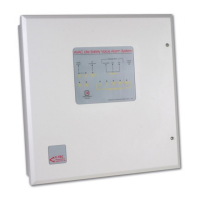
VAC VOICE ALARM SYSTEM
AVAC Installation and Maintenance Manual • Approved Document No. DAU0000402 Rev 6 • Page 16
CALIBRATING THE LOUDSPEAKER, FIRE MIC.
AND MASTER TO SLAVE CIRCUITS
The loudspeaker circuits are monitored by an intermittent 20 kHz tone which is passed down
the loudspeaker lines. Each circuit’s end of line device absorbs the tone and the current taken
is measured against the current drawn at system setup (known as the ‘reference’ value).
To store the reference value, the commissioning engineer must activate AVAC’s calibration
feature. Note that AVAC’s Fire Mic and Master to Slave circuits will be calibrated at the same
time and that prior to calibration the unit will always show a Fire Mic fault.
Calibration should ONLY be done when:-
1) Both loudspeaker circuits are complete i.e. all loudspeakers are connected,
appropriately tapped and verified and when the end of line devices (supplied) are
fitted after the last loudspeaker on each circuit.
2) Both loudspeaker circuits have been measured using a Loadmaster or
LCR meter and you have confirmed that the load on each circuit is no
greater than 60 watts (equivalent to a minimum impedance of 166 ohms).
3) The Fire Mic’s PTT input is in an untriggered state, i.e. only the 6k8 end of
line is present.
If calibration is done with the Fire Mic’s PTT input in a triggered
state, AVAC will calibrate the Fire Mic. circuit incorrectly and the Fire Mic. may not
work as expected.
4) The PLK2 Local Fault link has been temporarily removed from ALL slave
AVACs. Note you MUST refit the PLK2 Local Fault links to all slaves when calibration
is complete.
To start the calibration procedure, press and continue to hold down the calibration button
(SW1) on the Indicator PCB. The indicator light (IND1) on the Main PCB will pulse slowly. DO
NOT LET GO OF THE CALIBRATION BUTTON UNTIL THE INDICATOR LIGHT STARTS TO FLASH
MORE QUICKLY. Once the flashing speeds up, let go of the calibration button. When the
indicator light goes out, the calibration pr
ocedure is complete.
Always test the system for cor
r
ect operation after calibrating or recalibrating the circuits.
If any changes are made to the loudspeaker, fire mic. or master to slave circuits at any time - for
example, if a loudspeaker is added, r
emoved or its tapping is changed - the calibration pr
ocess
should be repeated to establish a new ‘reference’ level.
For mor
e specific loudspeaker wiring information, please refer to each loudspeaker’s
individual installation instructions for advice.
www.acornfiresecurity.com
www.acornfiresecurity.com