PTT
SIG 0V +V
M
AIN
PCB
1
L
ocal
Fault
OPTIONAL EXTRA AVAC MASTER UNITS
Fire Mic Input
To optional
next master
AVAC
FireMic
PLK2
Master/
Phantom
Page
PLK3
/10
Audio
Limit
PTT
SIG 0V +V
MAIN
PCB
2
Local
Fault
Fire Mic Input
FireMic
PLK2
Master/
Phantom
Page
PLK3
/
10
Audio
Limit
PTT
SIG 0V +V
MAIN
PCB
3
Local
Fault
Fire Mic Input
FireMic
PLK2
Master/
Phantom
Page
PLK3
/
10
Audio
Limit
FireMic
Page
BGM
FireMic
Page
BGM
FireMic
Page
B
GM
VA405
EMERGENCY
MICROPHONE
A C G H B
+ SIG 0
+ -
PTT
connect screens
Earth Stud
4 core or 2 x 2 core
A
VAC VOICE ALARM SYSTEM
AVAC Installation and Maintenance Manual • Approved Document No. DAU0000402 Rev 6 • Page 19
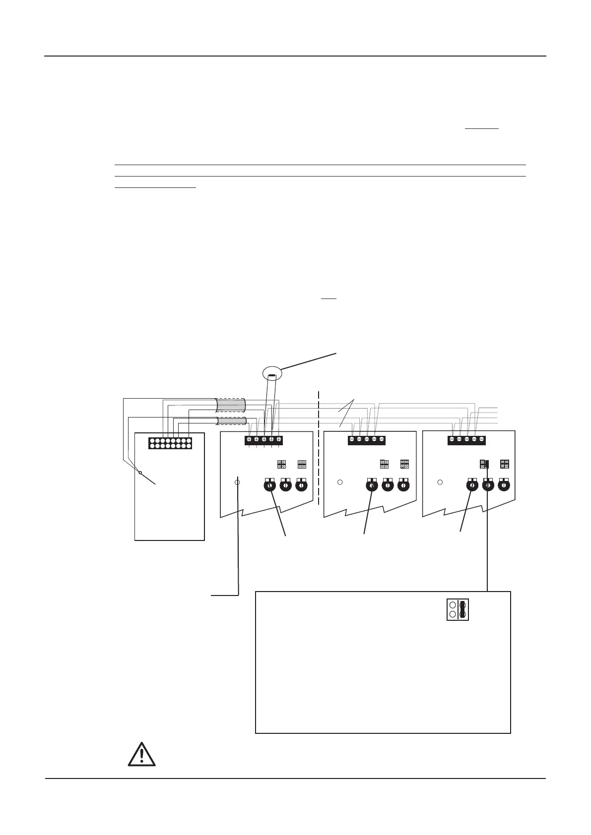
EMERGENCY (FIRE) MICROPHONE CONNECTION
If an emergency (fire) microphone is required, you must use a VA405 microphone. Only one
VA405 should be used per system. This can be daisychained to up to ten AVAC masters as illus-
trated below. Pressing the VA405’s push to talk button will override all other audio signals on
the system, including Evacuate and Alert messages, allowing live announcements to be made.
If an emer
gency microphone is NOT required, to prevent a fault condition occuring you must
fit the 6K8 0.25 W resistor (supplied in the accessory pack) across the PTT and 0V terminals at
the Fire Mic input.
If required, the volume of the microphone can be adjusted using the Fire Mic level control on
the Main PCB. Please note, should its volume be set too high, the audio limit LED on the
main PCB will illuminate red to indicate that the audio signal is being clipped. If this happens,
re-adjust the Fire Mic level control until you are satisfied with the sound quality and the limit
LED flickers red only very occasionally. Failure to do so could lead to poor sound quality.
If the microphone is too loud, too quiet or too distorted, the master output level of the
VA405 may need to be adjusted. Refer to the VA405 instructions for details.
Please note, to ensure the microphone is monitored correctly, the right hand PLK2 link
(
Master/Phantom) must only be fitted at the last master AVAC in the daisychain - see below
for details.
T
o ensure that the Emergency Mic. is
monitored correctly, the right hand
PLK2 link (
Master/Phantom) must
ONLY be fitted at the last master AVAC
in the daisychain. In this example, the
link would NOT be fitted at Main PCBs
1 and 2 but at PCB 3 only
.
Turn clockwise
to increase
emergency mic.
volume
Turn clockwise
to incr
ease
emer
gency
mic. volume
T
urn clockwise
to increase
emer
gency
mic. volume
Emergency microphone connection
The audio limit LED
illuminates red when the
audio signal is being clipped
due to the input or paging
volume being set too high.
If this occurs adjust the
level(s) accordingly until you
are satisfied with the sound
and the limit LED flickers
r
ed only ver
y occasionally
.
FireMic
PLK2
Local
Fault
Master/
Phantom
• If only one master AVAC is used, the Master/Phantom PLK2
link would be fitted on that A
VAC’s Main PCB.
•
The left hand PLK2 link (
Local Fault) is used for
master/slave interaction - see page 22 for details of when this
should be fitted.
Note that the Emergency Mic input will show a fault until the system has been
calibrated as detailed on page 16
6K8
If an emergency mic. is NOT used you MUST fit a 6K8
resistor (supplied) across the PTT and 0V terminals.
www.acornfiresecurity.com
www.acornfiresecurity.com