A
VAC VOICE ALARM SYSTEM
AVAC Installation and Maintenance Manual • Approved Document No. DAU0000402 Rev 6 • Page 18
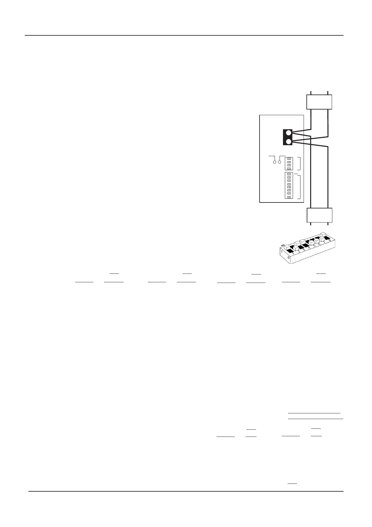
The analogue interface
AVACs analogue interface can be connected to any Apollo XP95,
Discovery or Xplorer analogue loop (see right).
If using this method, AVAC should be given a unique ID address
using the first seven segments of the eight way DIP switch (SW2)
on the Main PCB. When polled, the green polling LED will illumi-
nate momentarily to confirm the AVAC is working correctly.
Once on the loop, the AVAC emulates an Apollo sounder control
module and responds to fire alarm system commands as such,
playing an Alert message when an Alert (intermittent sounders)
command is received and an Evacuate message when an Evacuate
(continuous sounders) command is received.
In addition to its unique ID address, AVAC can be given a ‘group’
address using the four way DIP switch (SW1). A group address is
used by the fire detection system to activate the outputs of multi-
ple AVACs simultaneously.
If this facility is used, note that individual AVACs will continue to
r
eport back their status to the host fire detection system using
their unique ID address numbers as appropriate.
Setting AVAC’s unique ID address
Use bits 1 to 7 of the eight way DIP switch (SW2) to give AVAC a unique ID
address (i.e.13 in the example shown right with test enabled). This can be any
address between 1-126 (if group mode is not utilised) or 1-111 (if group mode
is utilised (see bottom of page).
ADDRESSABLE
LOOP
L
OOP
–
+
Polling
Test
Enable
SW1
SW2
Address
Group
1234567
8
1234
64
32
16
8
4
2
1
8
4
2
1
AVAC MAIN PCB
LOOP
ISOLATOR
L
OOP
ISOLATOR
I
nterfacing an Apollo
p
rotocol analogue panel
to the AVAC’s analogue
interface
1 1000000
2 0100000
3 1100000
4 0010000
5 1010000
6 0110000
7 1110000
8 0001000
9 1001000
10 0101000
11 1101000
12 0011000
13 1011000
14 0111000
15 1111000
16 0000100
17 1000100
18 0100100
19 1100100
20 0010100
21 1010100
22 0110100
23 1110100
24 0001100
25 1001100
26 0101100
27 1101100
28 0011100
29 1011100
30 0111100
31 1111100
32 0000010
65 1000001
66 0100001
67 1100001
68
0010001
69
1010001
70
0110001
71
1110001
72
0001001
73
1001001
74
0101001
75
1101001
76
0011001
77
1011001
78
0111001
79
1111001
80
0000101
81 1000101
82 0100101
83 1100101
84 0010101
85
1010101
86 0110101
87 1110101
88
0001101
89
1001101
90
0101101
91
1101101
92
0011101
93
1011101
94
0111101
95
1111101
96
0000011
97
1000011
98
0100011
99
1100011
100
0010011
101
1010011
102
0110011
103 1110011
104 0001011
Setting AVAC’s (optional) group address
Use bits 1 to 4 of the four way DIP switch
(SW1) to give an optional gr
oup address. A
group address can be any address between
112-126.
Mor
e than one A
VAC can have the
same group address.
105 1001011
106 0101011
107 1101011
108 0011011
109
1011011
110
0111011
111
1111011
112
0000111
113
1000111
114
0100111
115
1100111
116
0010111
117
1010111
118
0110111
119
1110111
120
0001111
121
1001111
122
0101111
123
1101111
124
0011111
125
1011111
126
0111111
(112-126 ar
e not available
if group addr
essing is used)
Address 1234567
112
1111
113
0111
114
1011
115
0011
116
1101
117
0101
118
1001
119
0001
120
1110
121
0110
122
1010
123
0010
124
1100
125
0100
126
1000
OFF
0000
Address 1234
Address 1234
SW2
Address 1234567
SW2
Address 1234567
SW2
Address 1234567
SW2
SW2
SW2
www.acornfiresecurity.com
www.acornfiresecurity.com