A
VAC VOICE ALARM SYSTEM
AVAC Installation and Maintenance Manual • Approved Document No. DAU0000402 Rev 6 • Page 24
DIGITAL MESSAGE SELECTION
The digital message store PCB is located on the main PCB. It comprises a non-volatile solid
state memory (on which the Evacuate, Alert and Test messages are stored in MP3 format), an
MP3 player and a volume control.
Message content
The general characteristics of the Evacuate and Alert digital messages meet BS 5839-8 (1998)
and consist of a siren sound to attract attention, brief silence, the body of the message fol-
lowed by another brief period of silence before the message is repeated.
The PLK4 option links on the Main PCB can be used to select different message arrangements to suit
various applications. For example, in single storey buildings, fitting Message Link 1 will remove the
statement “Do not use a lift” from all Evacuate messages whilst fitting Message Link 2 will report
Evacuate or Alert conditions as ‘situations’ rather than fires. If the Test message facility is used, fit-
ting Function
Link 4 will prompt the system to broadcast “The fire alarm test is now complete”
when the test trigger is removed. A full breakdown of the messages available can be found later in
this section.
Important:
To silence the Evacuate, Alert and/or Test Message:
• When the Conventional Interface is set to latching (PLK4 link 3 fitted) :
Operate the reset input.
• When the Conventional Interface is set to non-latching (PLK4 link 3 not fitted)
:
Remove the Evacuate, Alert and/or Test input stimulus.
Important: non-latching triggers are not fully compliant with BS 5839-8. However, if the triggers
(e.g. loop driven I/O units) are mounted adjacent to AVAC so that they form, in effect, one cabinet,
this is normally considered to be acceptable.
• When the Apollo loop interface is used:
Silence or reset the controlling FACIE which will issue the relevant control signal.
Evacuate message selection
Listed below are the four Evacuate messages available at the AVAC together with details of
the PLK4 option links you need to fit (or remove) to select them.
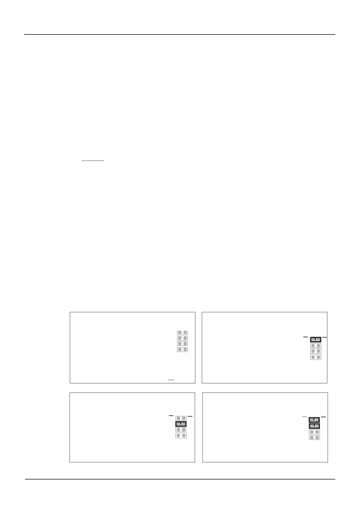
Evacuate message 1
Siren (three seconds silence),
Attention please, attention please.
Fir
e has been r
eported in the building.
Please leave the building immediately
by the near
est available exit.
Do not use a lift.
(three seconds silence then repeat)
Evacuate message 2
Sir
en
(thr
ee seconds silence)
Attention please, attention please.
Fire has been reported in the building.
Please leave the building immediately
by the near
est available exit.
(three seconds silence then repeat)
Evacuate message 3
Siren (three seconds silence)
Attention please, attention please.
A situation has arisen wher
e we need
to clear the building.
Please leave the building immediately
by the nearest available exit.
Do not use a lift.
(three seconds silence then repeat)
Evacuate message 4
Sir
en
(thr
ee seconds silence)
Attention please, attention please.
A situation has arisen where we need
to clear the building.
Please leave the building immediately
by the nearest available exit.
(thr
ee seconds silence then r
epeat)
1
2
3
4
1
2
3
4
PLK4
1
2
3
4
1
2
3
4
PLK4
Message Function
Message Function
1
2
3
4
1
2
3
4
PLK4
Message Function
1
2
3
4
1
2
3
4
PLK4
Message Function
1
2
3
4
1
2
3
4
PLK4
Message Function
Message links
1, 2, 3 & 4
not
fitted
Message
link 1 fitted
Message
link 2 fitted
Message links
1 & 2 fitted
1
2
3
4
1
2
3
4
PLK4
1
2
3
4
1
2
3
4
PLK4
Message Function
Message Function
1
2
3
4
1
2
3
4
PLK4
Message Function
1
2
3
4
1
2
3
4
PLK4
Message Function
1
2
3
4
1
2
3
4
PLK4
Message Function
1
2
3
4
1
2
3
4
PLK4
1
2
3
4
1
2
3
4
PLK4
Message Function
Message Function
1
2
3
4
1
2
3
4
PLK4
Message Function
1
2
3
4
1
2
3
4
PLK4
Message Function
1
2
3
4
1
2
3
4
PLK4
Message Function
1
2
3
4
1
2
3
4
PLK4
1
2
3
4
1
2
3
4
PLK4
Message Function
Message Function
1
2
3
4
1
2
3
4
PLK4
Message Function
1
2
3
4
1
2
3
4
PLK4
Message Function
1
2
3
4
1
2
3
4
PLK4
Message Function
www.acornfiresecurity.com
www.acornfiresecurity.com